Garmin GHP Reactor Hydraulic Autopilot Installation Instructions - Page 4
Installation Procedures
 |
View all Garmin GHP Reactor Hydraulic Autopilot manuals
Add to My Manuals
Save this manual to your list of manuals |
Page 4 highlights
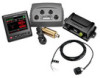
Item Description NMEA 2000 Ä network CCU Å Important Considerations The helm control and the CCU must be connected to a NMEA 2000 network using the included T-connectors (NMEA 2000 Connection Considerations). If there is not an existing NMEA 2000 network on your boat, you can build one using the supplied cables and connectors (Building a Basic NMEA 2000 Network for the Autopilot System). The CCU can be mounted in a non-submerged location near the center of the boat, in any orientation (CCU Mounting and Connection Considerations). The CCU must be located away from sources of magnetic interference. Installation Procedures CAUTION Always wear safety goggles, ear protection, and a dust mask when drilling, cutting, or sanding. NOTICE When drilling or cutting, always check what is on the opposite side of the surface. After you have planned the autopilot installation on your boat and satisfied all of the mounting and wiring considerations for your particular installation, you can begin mounting and connecting the components. Helm Control Installation You must Install the helm control by flush-mounting it in the dashboard near the helm and connecting it to a NMEA 2000 network. To use advanced features of the autopilot, optional NMEA 2000compatible or NMEA 0183-compatible devices, such as a wind sensor, water-speed sensor, or GPS device, can be connected to the NMEA 2000 network or connected to the helm control through NMEA 0183. Mounting the Helm Control NOTICE If you are mounting the device in fiberglass, when drilling the four pilot holes, it is recommended to use a countersink bit to drill a clearance counterbore through only the top gel-coat layer. This will help to avoid any cracking in the gel-coat layer when the screws are tightened. Stainless-steel screws may bind when screwed into fiberglass and overtightened. Garmin recommends applying an anti-seize lubricant to the screws before installing them. Before you can mount the helm control, you must select a mounting location (Helm Control Mounting Considerations). 1 Trim the flush-mount template and ensure it fits in the selected mounting location. The flush-mount template is included in the helm control product box. 2 Secure the template to the selected mounting location. 3 If you plan to cut the hole with a rotary cutting tool instead of a 90 mm (3.5 in.) hole saw, use a 10 mm (3/8 in.) drill bit to drill a pilot hole as indicated on the template to begin cutting the mounting surface. 4 Using the hole saw or rotary cutting tool, cut the mounting surface along the inside of the dashed line indicated on the template. 5 If necessary, use a file and sandpaper to refine the size of the hole. 6 Place the helm control into the cutout to confirm that the four mounting holes on the template are in the correct locations. 7 If the mounting holes are not correct, mark the correct locations of the four mounting holes. 8 Remove the helm control from the cutout. 9 Drill the four 2.8 mm (7/64 in.) pilot holes. If you are mounting the helm control in fiberglass, you should use a countersink bit as advised in the notice. 10Remove the remainder of the template. 11Place the included gasket on the back of the device. You can apply marine sealant around the gasket to prevent leakage behind the dashboard (optional). 12Place the helm control into the cutout. 13Securely fasten the helm control to the mounting surface using the supplied screws. If you are mounting the helm control in fiberglass, you should use an anti-seize lubricant as advised in the notice. 14Snap the decorative bezel into place. À Mounting the CCU 1 Determine the mounting location. 2 Using the CCU as a template, mark the two pilot hole locations on the mounting surface. 3 Using a 3 mm (1/8 in.) bit, drill the pilot holes. 4 Use the included screws to attach the CCU to the mounting surface. ECU Installation Mounting the ECU Before you can mount the ECU, you must select a location and determine the correct mounting hardware (ECU Mounting and Connection Considerations). 1 Hold the ECU in the intended mounting location and mark the locations of the mounting holes on the mounting surface, using the ECU as a template. 2 Using a drill bit appropriate for the mounting surface and selected mounting hardware, drill the four holes through the mounting surface. 3 Secure the ECU to the mounting surface using the selected mounting hardware. Connecting the ECU to Power WARNING When connecting the power cable, do not remove the in-line fuse holder. To prevent the possibility of injury or product damage caused by fire or overheating, the appropriate fuse must be in place as indicated in the product specifications. In addition, connecting the power cable without the appropriate fuse in place will void the product warranty. You should connect the ECU power cable directly to the boat battery, if possible. Although it is not recommended, if you connect the power cable to a terminal block or other source, you must connect it through a 40 A fuse. 4
-
 1
1 -
 2
2 -
 3
3 -
 4
4 -
 5
5 -
 6
6 -
 7
7 -
 8
8 -
 9
9 -
 10
10 -
11
-
12
-
13
-
14
 |
 |
