Garmin GHP Reactor Hydraulic Autopilot Installation Instructions - Page 5
Installing the Pump
 |
View all Garmin GHP Reactor Hydraulic Autopilot manuals
Add to My Manuals
Save this manual to your list of manuals |
Page 5 highlights
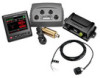
If you plan to route the ECU power through a breaker or a switch near the helm, you should consider using an appropriately sized relay and control wire instead of extending the ECU power cable. 1 Route the connector-terminated end of the ECU power cable to the ECU, but do not connect it to the ECU. 2 Route the bare-wire end of the ECU power cable to the boat battery. If the wire is not long enough, it can be extended (Power Cable Extensions). 3 Connect the black wire (-) to the negative (-) terminal of the battery, and connect the red wire (+) to the positive (+) terminal of the battery. 4 After you install all of the other autopilot components, connect the power cable to the ECU. Power Cable Extensions If necessary, the power cable can be extended using the appropriate wire gauge for the length of the extension. Item À Á  Description Fuse Battery 9 ft. (2.7 m) no extension Item Description Splice 10 AWG (5.26 mm²) extension wire Fuse 8 in. (20.3 cm) Battery 8 in. (20.3 cm) Up to 15 ft. (4.6 m) Item Description Splice 8 AWG (8.36 mm²) extension wire Fuse 8 in. (20.3 cm) Battery 8 in. (20.3 cm) Up to 23 ft. (7 m) Item À Á  Description Splice 6 AWG ( 13.29 mm²) extension wire Fuse Item Ã Ä Å Æ Description 8 in. (20.3 cm) Battery 8 in. (20.3 cm) Up to 36 ft. (11 m) Installing the Pump The pump (sold separately) must be installed in your hydraulic steering lines so the GHP Reactor Hydraulic autopilot can steer your boat. When you purchase a pump sold by Garmin, it will have the correct cables, connectors, and instructions. Follow the installation instructions provided with your pump to mount it and connect it to your hydraulic steering system correctly. Bleeding the Hydraulics NOTICE This is a general procedure for bleeding a hydraulic steering system. Refer to the instructions provided by the manufacturer of the steering system for more-specific information about bleeding the system. Before you bleed the hydraulic system, you should verify that all hose connections are complete and fully tightened. 1 Select an option: • If the helm reservoir contains insufficient fluid, fill it as needed. • If the helm reservoir contains excess fluid, remove the excess to avoid fluid overflow during the bleeding process. 2 Insert a bypass hose between the cylinder bleed ports. TIP: If you use a clear plastic hose for this bypass, you can observe air bubbles during the bleeding processes. 3 Manually steer the helm fully to port. 4 Open both bypass valves at the cylinder fittings. 5 Manually turn the helm slowly to port over three minutes. TIP: You can stop turning when you no longer see air moving through the bypass hose. 6 Turn on the autopilot system and disable the Shadow Drive. You can refer to the autopilot system documentation for more information on disabling the Shadow Drive. 7 Hold (port) on the helm control for at least 10 seconds. TIP: You can stop holding when you no longer see air moving through the bypass hose. 8 Close both bypass valves at the cylinder fittings. 9 If necessary, add fluid to the helm reservoir. 10Repeat steps 3 through 9 for the starboard side. 11Hold (port) on the helm control until steering stops and Hydraulic Pump Stall is shown on the helm control. 12Hold (starboard) on the helm control until steering stops and Hydraulic Pump Stall is shown on the helm control. 13Select an option: • If Hydraulic Pump Stall is not shown within 2 to 3 seconds after the cylinder stops, repeat steps 1-13 to bleed the system again. • If Hydraulic Pump Stall is shown within 2 to 3 seconds after the cylinder stops, the system bleed completed successfully. After hydraulic bleeding is complete, you can re-enable the Shadow Drive. 5
-
 1
1 -
 2
2 -
 3
3 -
 4
4 -
 5
5 -
 6
6 -
 7
7 -
 8
8 -
 9
9 -
 10
10 -
 11
11 -
12
-
13
-
14
 |
 |
