Garmin GMR 1226 xHD2 Open Array Radar and Pedestal Installation Instructions - Page 1
Garmin GMR 1226 xHD2 Open Array Radar and Pedestal Manual
 |
View all Garmin GMR 1226 xHD2 Open Array Radar and Pedestal manuals
Add to My Manuals
Save this manual to your list of manuals |
Page 1 highlights
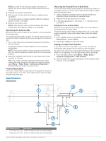
GMR™ 420/620/1220/2520 xHD2 Series Installation Instructions To obtain the best performance and to avoid damage to your boat, install the device according to these instructions. Read all installation instructions before proceeding with the installation. If you experience difficulty during the installation, contact Garmin® Product Support. Important Safety Information WARNING See the Important Safety and Product Information guide in the product box for product warnings and other important information. The radar transmits electromagnetic energy. Ensure that the radar is installed according to the recommendations in these instructions and that all personnel are clear of the path of the radar beam before transmitting. When properly installed and operated, the use of this radar conforms to the requirements of ANSI/IEEE C95.1-1992 Standard for Safety Levels with Respect to Human Exposure to Radio Frequency Electromagnetic Fields. When the radar is transmitting, do not look directly at the antenna at close range; eyes are the most sensitive part of the body to electromagnetic energy. When connecting the power cable, do not remove the in-line fuse holder. To prevent the possibility of injury or product damage caused by fire or overheating, the appropriate fuse must be in place as indicated in the product specifications. In addition, connecting the power cable without the appropriate fuse in place will void the product warranty. CAUTION This device should be used only as a navigational aid. Do not attempt to use the device for any purpose requiring precise measurement of direction, distance, location, or topography. Always wear safety goggles, ear protection, and a dust mask when drilling, cutting, or sanding. NOTICE When drilling or cutting, always check what is on the opposite side of the surface. Registering Your Device Help us better support you by completing our online registration today. • Go to http://my.garmin.com. • Keep the original sales receipt, or a photocopy, in a safe place. Contacting Garmin Product Support • Go to www.garmin.com/support and click Contact Support for in-country support information. • In the USA, call (913) 397.8200 or (800) 800.1020. • In the UK, call 0808 2380000. • In Europe, call +44 (0) 870.8501241. Tools Needed • #2 Phillips screwdriver • 5 mm hex wrench • Drill and 15.0 mm (19/32 in.) drill bit • 17 mm (21/32 in.) wrench and torque wrench • A length of 3.31 mm² (12 AWG) copper wire to ground the radar housing (and voltage converter, if applicable). • Marine sealant Mounting Considerations When selecting a mounting location, observe these considerations. • It is highly recommended that the device is mounted out of range of people, with the vertical beam width above head height. To avoid exposure to harmful radio frequency (RF) levels, the device should not be mounted closer to people than the maximum safe distance value listed in the product specifications. • The device should be mounted high above the ship's keel line with minimal blockage of the radar beam. Obstructions may cause blind and shadow sectors, or generate false echoes. The higher the installation position, the farther the radar can detect targets. • The device should be mounted on a flat surface or a platform that is parallel to the vessel's water line and is sturdy enough to support the device's weight. The weight for each model is listed in the product specifications. • The radar beam spreads vertically 11.5° above and 11.5° below the radar's radiating element. On vessels with À higher bow angles at cruise speed, the installation angle can be lowered to point the beam slightly downward to the waterline while at rest. Shims can be used if necessary. • The device should be mounted away from heat sources, such as smoke stacks and lights. • The device should be mounted at a different level than horizontal spreaders and mast crosstrees. • To avoid interference with a magnetic compass, the device should not be mounted closer to a compass than the compass-safe distance value listed in the product specifications. • Other electronics and cables should be mounted more than 2 m (6.5 ft.) from the radar beam path. • GPS antennas should be either above or below the radar beam path. • The device should be mounted at least 1 m (40 in.) from any transmitting equipment. • The device should be mounted at least 1 m (40 in.) away from cables carrying radio signals such as VHF radios, cables, and antennas. • The device should be mounted at least 2 m (6.5 ft.) away from Single Side Band (SSB) radios. Preparing the Surface and the Radar for Mounting Before you can mount the radar, you must choose a suitable mounting location (Mounting Considerations, page 1). 1 Select an option: • If you are using a pre-drilled Garmin compatible Furuno® or Raymarine® mount, proceed to step 3. July 2015 Printed in Taiwan 190-01818-02_0B
-
 1
1 -
 2
2 -
 3
3 -
 4
4 -
 5
5 -
 6
6 -
 7
7 -
8
 |
 |
