Garmin GMR 1226 xHD2 Open Array Radar and Pedestal Installation Instructions - Page 6
Physical Specifications, Electrical Specifications
 |
View all Garmin GMR 1226 xHD2 Open Array Radar and Pedestal manuals
Add to My Manuals
Save this manual to your list of manuals |
Page 6 highlights
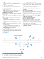
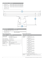
Item Measurement 25 mm (1 in.) Â 125 mm (4 15/16 in.) Ã Ä 50 mm (1 15/16 in.) Å 150 mm (5 29/32 in.) Æ 140 mm (5 1/2 in.) Ç 200 mm (7 7/8 in.) Description Center of rotation to the inner rear mounting holes. Center of rotation to the inner front mounting holes. Center of rotation to the outer rear mounting holes. Center of rotation to the outer front mounting holes. Item Measurement Description À 4 ft. models: 132.7 cm (4 ft. 4 1/4 in.) Antenna length. 6 ft. models: 193.7 cm (6 ft. 4 1/4 in.) Á 45.1 cm (17 3/4 in.) Base of the pedestal to the top of the antenna. Â 31.8 cm (12 1/2 in.) Width of the pedestal. Physical Specifications Electrical Specifications Specification Measurement Pedestal weight 21.4 kg (47.1 lb) Antenna weight 4 ft. antenna: 5.5 kg (12.2 lb.) 6 ft. antenna: 7.7 kg (16.9 lb.) Power cable length 15 m (49 ft. 3 in.) Network cable length 15 m (49 ft. 3 in.) Antenna rotation speed 24 rpm and 48 rpm Max wind load 80 kn Temperature range From -15 to 70ºC (5 to 158ºF) Humidity 95% at 35°C (95°F) Water resistance IEC 60529 IPX6 (protected against heavy seas) Bearing accuracy 0.25º Specification Minimum safe operating distance* Compass-safe distance Measurement GMR 424 xHD2 • 100 W/m²: 1.22 m (48 in.) • 10 W/m²: 3.90 m (154 in.) GMR 426 xHD2 • 100 W/m²: 1.54 m (61 in.) • 10 W/m²: 4.85 m (191 in.) GMR 624 xHD2 • 100 W/m²: 1.50 m (59 in.) • 10 W/m²: 4.70 m (185 in.) GMR 626 xHD2 • 100 W/m²: 1.90 m (75 in.) • 10 W/m²: 5.90 m (232 in.) GMR 1224 xHD2 • 100 W/m²: 2.10 m (83 in.) • 10 W/m²: 6.65 m (262 in.) GMR 1226 xHD2 • 100 W/m²: 2.65 m (104 in.) • 10 W/m²: 8.50 m (335 in.) GMR 2524 xHD2 • 100 W/m²: 2.19 m (86 in.) • 10 W/m²: 6.92 m (272 in.) GMR 2526 xHD2 • 100 W/m²: 2.75 m (108 in.) • 10 W/m²: 8.70 m (342 in.) Standard compass: 90 cm (35 7/16 in.) Standby steering and emergency compasses: 80 cm (31 1/2 in.) 6 GMR 420/620/1220/2520 xHD2 Series Installation Instructions
-
 1
1 -
 2
2 -
 3
3 -
 4
4 -
 5
5 -
 6
6 -
 7
7 -
 8
8
 |
 |
