Garmin GMR 18 HD3 Installation Instructions - Page 9
Radar Operation
 |
View all Garmin GMR 18 HD3 manuals
Add to My Manuals
Save this manual to your list of manuals |
Page 9 highlights
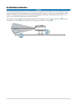
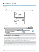
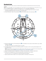
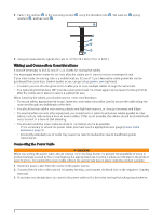
Power Cable Extensions Connecting the power cable directly to the battery is recommended. If it is necessary to extend the cable, the appropriate gauge of wire must be used for the length of the extension. Distance Wire Gauge 2 m (6.5 ft.) 16 AWG (1.31 mm²) 4 m (13 ft.) 14 AWG (2.08 mm²) 6 m (19.5 ft.) 12 AWG (3.31 mm²) Garmin Network Considerations This radar connects to compatible Garmin devices to share radar data. When connecting this radar to a Garmin network device, observe these considerations. There are two sizes of Garmin network cable connectors that may be used on various devices in your system. • The smaller network connectors are present on many newer Garmin devices. ◦ These connectors are similar in size and shape to a NMEA 2000® network connector, but the pins and keys are different and do not allow you to connect to a NMEA 2000 network. ◦ You can connect devices with the smaller network connectors to one another using a Garmin network cable with smaller connectors. ◦ This radar has a smaller Garmin network connector and is packaged with a cable that has smaller connectors on both ends. • The larger network connectors are present on most older Garmin devices. ◦ These connectors look similar to traditional RJ45 network connectors. ◦ You can connect devices with the larger network connectors to one another using a Garmin network cable with larger connectors. ◦ To connect this radar to an older device with a larger connector, you can use the included adapter. This radar provides data to a connected chartplotter. When the chartplotter is connected to other Garmin network devices, it shares the radar data over the network with all of the compatible connected devices. Additional Garmin network cables, cable extensions, and adapters are available from your Garmin dealer, or go to buy.garmin.com. Radar Operation All functions of this radar are controlled with your Garmin chartplotter. See the Radar section of your chartplotter's owner's manual for operating instructions. To download the latest manual, go to support.garmin .com/manuals. If you have more than one radar on your boat, you must be viewing the radar screen for the radar you want to configure. Measuring and Setting the Front-of-Boat Offset The front-of-boat offset compensates for the physical orientation of the radar scanner on a boat, if the radar scanner does not align with the bow-stern axis. The front-of-boat offset setting configured for use in one radar mode is applied to every other radar mode and to the radar overlay. 1 Using a magnetic compass, take an optical bearing of a stationary target located within viewable range. 2 Measure the target bearing on the radar. 3 If the bearing deviation is more than +/- 1 degree, set the front-of-boat offset. 4 From a radar screen, select Options > Radar Setup > Installation > Front of Boat. 5 Select Up or Down to adjust the offset. 9
-
 1
1 -
2
-
3
-
 4
4 -
 5
5 -
 6
6 -
 7
7 -
 8
8 -
 9
9 -
 10
10 -
 11
11 -
 12
12 -
 13
13 -
 14
14
 |
 |
