Garmin GMR 24 xHD Radome Installation Instructions - Page 3
Connecting the Power Cable, Connecting to a Device or to the Marine, Network, Radar Operation,
 |
View all Garmin GMR 24 xHD Radome manuals
Add to My Manuals
Save this manual to your list of manuals |
Page 3 highlights
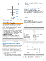
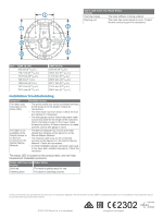
10 Using a torque wrench, tighten the nuts from 13. 7 to 18. 6 Nm (10 to 14 lbf-in. ) of force. Connecting the Power Cable WARNING When connecting the power cable, do not remove the in-line fuse holder. To prevent the possibility of injury or product damage caused by fire or overheating, the appropriate fuse must be in place as indicated in the product specifications. In addition, connecting the power cable without the appropriate fuse in place voids the product warranty. 1 Route the power cable from the device to the power source. 2 Connect the red wire to the positive (+) battery terminal, and connect the black wire to the negative (-) battery terminal. 3 If you have not already done so, connect the power cable to the device by turning the locking ring clockwise. Power Cable Extensions Connecting the power cable directly to the battery is recommended. If it is necessary to extend the cable, the appropriate gauge of wire must be used for the length of the extension. Distance 2 m (6. 5 ft. ) 4 m (13 ft. ) 6 m (19 ft. ) Wire Gauge 16 AWG (1. 31 mm²) 14 AWG (2. 08 mm²) 12 AWG (3. 31 mm²) Connecting to a Device or to the Marine Network You can connect the radar either directly to a radar-compatible Garmin device or to a Garmin Marine Network to share radar information with all connected devices. NOTE: Not all Garmin devices are compatible with the Garmin Marine Network. See the installation instructions or owner's manual provided with your device for more information. 1 Route the network cable to your compatible Garmin device. 2 If you have not already done so, install the locking rings and o-rings on the end of the network cable. 3 Select an option: • If the Garmin device is not compatible with the Garmin Marine Network, connect the network cable to the port labeled RADAR. • If the device is compatible with the Garmin Marine Network, connect the network cable to the port labeled NETWORK. Radar Operation All functions of the Garmin radome are controlled with your Garmin chartplotter. See the Radar section of your chartplotter's manual for operating instructions. To download the latest manual, go to www.garmin.com/ support / . Measuring the Potential Front-of-Boat Offset The front-of-boat offset compensates for the physical location of the radar scanner on a boat, if the radar scanner does not align with the bow-stern axis. 1 Using a magnetic compass, take an optical bearing of a stationary target located within viewable range. 2 Measure the target bearing on the radar. 3 If the bearing deviation is more than +/- 1°, set the front-of- boat offset. Setting the Front-of-Boat Offset Before you can set the front-of-boat offset, you must measure the potential front-of-boat offset. The front-of-boat offset setting configured for use in one radar mode is applied to every other radar mode and to the Radar overlay. Select Up or Down to adjust the offset. Specifications Specification GMR 18 xHD weight GMR 24 xHD weight Temperature range Case material Default antenna rotation speed Alternative antenna rotation speed Power input source Power output RF transmit frequency Compass-safe distance GMR 18 xHD beam width GMR 24 xHD beam width Maximum range Minimum range Range discrimination Range scales Detailed Dimensions Measurement 7. 7 kg (16. 95 lb. ) 9. 5 kg (20. 9 lb. ) From -15 to 70°C (from 5 to 158°F) Thermoplastic resin 48 RPM 24 RPM From 11 to 35 Vdc, 3. 5 A, 4 kW peak 9410 MHz nominal 1 m (3. 28 ft. ) 3. 7 degrees 5. 2 degrees 48 nm 20 m (66 ft. ) 16 m (52. 5 ft. ) 0. 125, 0. 25, 0. 5, 0. 75, 1, 1. 5, 2, 3, 4, 6, 8, 12, 16, 24, 36, and 48 nm Item Length À (width) Á (height) GMR 18 xHD 508. 2 mm (20 in. ) 504. 7 mm (19 7/8 in. ) 248. 3 mm (9 ¾ in. ) GMR 24 xHD 645. 4 mm (25 7/16 in. ) 642. 5 mm (25 5/16 in. ) 250. 3 mm (9 7/8 in. ) 3
-
 1
1 -
 2
2 -
 3
3 -
 4
4
 |
 |
