Garmin GMR 6kW Pedestal xHD Installation Instructions
Garmin GMR 6kW Pedestal xHD Manual
 |
View all Garmin GMR 6kW Pedestal xHD manuals
Add to My Manuals
Save this manual to your list of manuals |
Garmin GMR 6kW Pedestal xHD manual content summary:
- Garmin GMR 6kW Pedestal xHD | Installation Instructions - Page 1
GMR 400/600/1200 xHD radar according to the following instructions. If you experience difficulty installing the chartplotter, seek the assistance of a professional installer, or contact Garmin® Product Support. Before installing your GMR 400/600/1200 xHD look directly at the antenna at close range, - Garmin GMR 6kW Pedestal xHD | Installation Instructions - Page 2
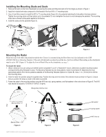
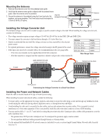
states maximum distances from the antenna at which Radio Frequency (RF) levels can be expected. ◦◦ GMR 404 xHD (100W/m squared = 55 in. [1.4 m]) (10W/m squared = 178 in. [4.5 m]) ◦◦ GMR 406 xHD (100W/m squared = 65 in. [1.7 m]) (10W/m squared = 200 in. [5.1 m]) ◦◦ GMR 604 xHD (100W/m squared = 67 in - Garmin GMR 6kW Pedestal xHD | Installation Instructions - Page 3
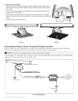
step two if you are using a pre-drilled Garmin compatible Furuno® or Raymarine® mount.) Determine a strap. Position the strap over the ends of the antenna mount as shown in Figure 5. Ensure that you position Figure 4 GMR 400/600/1200 xHD Installation Instructions Figure 5 Figure 6 flat washer spring - Garmin GMR 6kW Pedestal xHD | Installation Instructions - Page 4
a marine sealant. ◦◦ You can purchase additional cable grommets through Garmin or a Garmin dealer. • Use the optional field-installable RJ-45 network connector (included) to create a custom-length Garmin Marine Network cable if needed (see page 8). 4 GMR 400/600/1200 xHD Installation Instructions - Garmin GMR 6kW Pedestal xHD | Installation Instructions - Page 5
studs, an M10 nut, and flat washer. GMR 400/600/1200 xHD radar To water ground Garmin marine network cable Radar power cable 7.5 A fuse Power converter + 10-40 Vdc (20-40 Vdc for the GMR 1204 - and 1206) To RF ground Power Wiring Diagram GMR 400/600/1200 xHD Installation Instructions 5 - Garmin GMR 6kW Pedestal xHD | Installation Instructions - Page 6
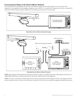
45 marine network cable to an open RJ-45 socket on the GMS 10 network expander. Tighten the RJ-45 locking ring clockwise until it is firmly sealed. GMR 400/600/1200 xHD radar Garmin Marine Networkcompatible chartplotter GMR 400/600/1200 xHD radar Stand-Alone Garmin Marine Network Example GSD 22 - Garmin GMR 6kW Pedestal xHD | Installation Instructions - Page 7
instructions in the chartplotter owner's manual. Download the latest software from www.garmin.com. Entering the Radar Antenna Size Using a chartplotter, specify the size of your radar antenna , press the Setup softkey to open the setup page. 2. From GMR 400/600/1200 xHD Installation Instructions 7 - Garmin GMR 6kW Pedestal xHD | Installation Instructions - Page 8
Green Orange White/Brown White/Brown Brown Brown Position 8 Position 1 NOTE: The Garmin Marine Network requires cross-over cables not exceeding 100 meters between devices. When constructing . Use caution to avoid damaging the copper tape. 8 GMR 400/600/1200 xHD Installation Instructions - Garmin GMR 6kW Pedestal xHD | Installation Instructions - Page 9
with a 15 mm wrench. Be careful not to overtighten the nut. 5. Install the O-ring onto the housing. The cable is now ready to use. O-Ring GMR 400/600/1200 xHD Installation Instructions 9 - Garmin GMR 6kW Pedestal xHD | Installation Instructions - Page 10
mm) 5 /29 32 in. (150 mm) 5 /33 64 in. (140 mm) 7 7/8 in. (200 mm) 12 /11 32 in. (313.5 mm) L 12 7/8 in. (326.8 mm) Model GMR 404/604/1204 xHD GMR 406/606/1206 xHD L 51 /19 32 in. (1310 mm) 75 /45 64 in. (1923 mm) 10 GMR 400/600/1200 xHD Installation Instructions - Garmin GMR 6kW Pedestal xHD | Installation Instructions - Page 11
and rain clutter 4 ft Open-Array Antenna Type: End-fed slotted Manual (GPSMAP 3000 series chartplotters) Antenna RPM: Selectable to 24 or 48 rpm MARPA: Tracks up to 10 MARPA targets for radar plotting and collision avoidance (Heading sensor is required) GMR 400/600/1200 xHD Installation Instructions - Garmin GMR 6kW Pedestal xHD | Installation Instructions - Page 12
antenna. GMR 400/600/1200 xHD radar is in compliance with the essential requirements and other relevant provisions of Directive 1999/5/EC. To view the full Declaration of Conformity, see the Garmin Web site for your Garmin product: www.garmin.com. 12 GMR 400/600/1200 xHD Installation Instructions - Garmin GMR 6kW Pedestal xHD | Installation Instructions - Page 13
of the United States of America. Limited Warranty All Garmin marine radomes and open array radomes are warranted to be free from defects in . To obtain warranty service, contact your local Garmin authorized dealer or call Garmin Product Support for shipping instructions and an RMA tracking - Garmin GMR 6kW Pedestal xHD | Installation Instructions - Page 14
consent of Garmin. Garmin hereby grants permission to download a single copy of this manual onto a hard Garmin products. Garmin®, the Garmin logo, and GPSMAP® are trademarks of Garmin Ltd. or its subsidiaries, registered in the USA and other countries. GMR™ and myGarmin™ are trademarks of Garmin
-
 1
1 -
 2
2 -
 3
3 -
 4
4 -
 5
5 -
 6
6 -
 7
7 -
8
-
9
-
10
-
11
-
12
-
13
-
14
 |
 |
December 2010
190-01266-02 Rev. B
Printed in Taiwan
GMR
™
400/600/1200 xHD Radar Installation Instructions
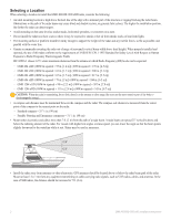
Properly install your GMR 400/600/1200 xHD radar according to the following instructions.
If you experience difficulty installing the
chartplotter, seek the assistance of a professional installer, or contact Garmin
®
Product Support.
Before installing your GMR 400/600/1200 xHD radar, confirm that the package contains the items listed on the box. If any parts are missing,
contact your Garmin dealer immediately.
WARNING:
Always wear safety goggles, ear protection, and a dust mask when drilling, cutting, or sanding.
WARNING:
The selected radar mounting location must be able to hold the weight of the radar and withstand any inertial forces.
WARNING:
The radar transmits electromagnetic energy. It is important that the radar is turned off or the DC power input is disconnected when
personnel are required to come close to the radar to perform work on the radar assembly or associated equipment. Electromagnetic energy is harmful.
CAUTION:
When the radar is transmitting, do not look directly at the antenna at close range, because the eyes are the most sensitive part of the body to
electromagnetic energy.
NOTICE:
When drilling or cutting, always check the opposite side of the drilling or cutting surface.
Product Registration
Help us better support you by completing our online registration today. Go to
. Keep the original sales receipt, or a
photocopy, in a safe place.
Contact Garmin
Contact Garmin Product Support if you have any questions while installing your GMR 400/600/1200 xHD radar. In the USA, go to
www.garmin.com/support
, or contact Garmin USA by phone at (913) 397.8200 or (800) 800.1020.
In the UK, contact Garmin (Europe) Ltd. by phone at 0808 2380000.
In Europe, go to
www.garmin.com/support
and click
Contact Support
for in-country support information, or contact Garmin (Europe) Ltd. by
phone at +44 (0) 870.8501241.
Needed Tools
For Installing the Radar:
•
#2 Phillips screwdriver
•
5 mm Allen wrench
•
Drill and drill bits
•
Wrench and socket set
For Installing the Optional Field-Installable RJ-45 Network Connector:
•
Knife
•
Pliers
•
15 mm wrench
•
AMP modular-plug hand tool and die set or compatible equivalent