Garmin GMR 6kW Pedestal xHD Installation Instructions - Page 5
Connecting the Radar to Power Through the Voltage Converter
 |
View all Garmin GMR 6kW Pedestal xHD manuals
Add to My Manuals
Save this manual to your list of manuals |
Page 5 highlights
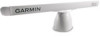
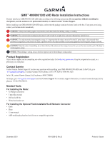
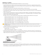
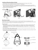
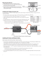
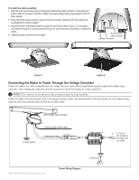
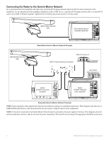
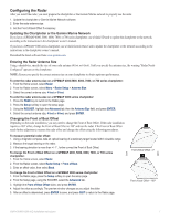
To install the cable assembly: 1. Align the notch and locking ring on the power cable to the power connector. Press the 2-pin power cable to the power connector. Tighten the power-cable locking ring clockwise until it is firmly sealed.. 2. Press the RJ-45 marine network cable to the RJ-45 socket. Tighten the RJ-45 locking ring clockwise until it is firmly sealed. 3. Route the power and network cables through the front of the radar (Figure 7), or through a hole drilled through the mounting surface (Figure 8). Avoid excessively bending or twisting the cables. 4. Install the hatch on the front of the radar. RJ-45 network cable connector Power connector Figure 7 Figure 8 Connecting the Radar to Power Through the Voltage Converter Connect the radar power cable (red and black) to the voltage converter output cable (red and black) using the supplied heat-shrink crimp connectors. After crimping the connections, heat the connectors to shrink the housing for a water resistant fit. Notice: If you choose to cut the radar power cable, you must reconnect the in-line fuse holder. Connect the radar to the water ground of the vessel using an 8 gauge copper cable (not included). Secure the ground wire to the radar housing using one of the four mounting studs, an M10 nut, and flat washer. GMR 400/600/1200 xHD radar To water ground Garmin marine network cable Radar power cable 7.5 A fuse Power converter + 10-40 Vdc (20-40 Vdc for the GMR 1204 - and 1206) To RF ground Power Wiring Diagram GMR 400/600/1200 xHD Installation Instructions 5
-
 1
1 -
 2
2 -
 3
3 -
 4
4 -
 5
5 -
 6
6 -
 7
7 -
 8
8 -
 9
9 -
 10
10 -
 11
11 -
12
-
13
-
14
 |
 |