Garmin Montana 750i MotorcycleATV Mount Instructions - Page 3
Specifications, Limited Warranty - accessories
 |
View all Garmin Montana 750i manuals
Add to My Manuals
Save this manual to your list of manuals |
Page 3 highlights
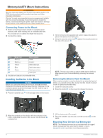
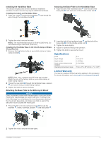
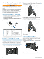
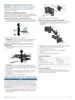
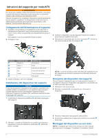
Installing the Handlebar Base The device includes parts for two handlebar installation solutions. Custom mounts may require additional hardware. Installing the U-bolt and Handlebar Base 1 Place the U-bolt around the handlebar , and thread the ends through the handlebar base . Attaching the Base Plate to the Handlebar Base 1 Align the ball of the handlebar base and the ball of the base plate with each end of the double-socket arm . 2 Tighten the nuts to secure the base. NOTE: The recommended torque is 50 lbf-in (5.65 N-m). Do not exceed torque of 80 lbf-in (9.04 N-m). Installing the Handlebar Base to the Clutch-Clamp or BrakeClamp Brackets 1 Remove the two factory bolts on your clutch-clamp or brake- clamp bracket . 2 Insert the ball of the handlebar base and the ball of the base plate into the double-socket arm . 3 Tighten the knob slightly. 4 Adjust for optimal viewing and operation. 5 Tighten the knob to secure the mount. Specifications Fuse Input voltage Input current Input current without device installed Operating temperature range 3 A 10 to 30 V 1.5 A Max. 0.5 mA Max. From -20º to 60ºC (from -4º to 140ºF) NOTE: Both 1/4 in. standard and M6 bolts are included. Match the size of the factory bolts on your clutch-clamp or brake-clamp bracket. 2 Thread the new bolts through the handlebar base, spacers , and clutch-clamp or brake-clamp bracket. 3 Tighten the bolts to secure the base. Attaching the Base Plate to the Motorcycle Mount NOTICE Direct, sustained contact with the base plate, or any part of the motorcycle, may damage the mount over time. To prevent this kind of damage, you must place the mounting spacers between the mount and base plate, and make sure that no part of the device or mount touches the motorcycle. 1 Thread the M4 x 20 mm panhead screws through the washers , cradle, bushings, spacers , and base plate . Limited Warranty The Garmin standard limited warranty applies to this accessory. For more information, go to www.garmin.com/support/warranty. 2 Tighten the nuts to secure the base plate. Installation Instructions 3
-
 1
1 -
 2
2 -
 3
3 -
 4
4 -
 5
5 -
 6
6 -
 7
7 -
 8
8 -
 9
9 -
10
-
11
-
12
-
13
-
14
-
15
-
16
-
17
-
18
-
19
-
20
-
21
-
22
-
23
-
24
 |
 |
