Garmin VHF 115 Installation Instructions PDF
Garmin VHF 115 Manual
 |
View all Garmin VHF 115 manuals
Add to My Manuals
Save this manual to your list of manuals |
Garmin VHF 115 manual content summary:
- Garmin VHF 115 | Installation Instructions PDF - Page 1
VHF 115/215 AIS SERIES INSTALLATION INSTRUCTIONS Important Safety Information WARNING See the Important Safety and Product Information guide WARNING Radio operators with cardiac pacemakers, life-support machines, or electrical medical equipment should not be exposed to excessive radio-frequency - Garmin VHF 115 | Installation Instructions PDF - Page 2
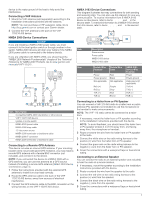
adhesive on the back. Make sure you remove the protective liner before installing them on the device. 13Place the device in the cutout. 14Secure microphone on a VHF 215 AIS radio (microphone relocation kit sold separately). This connector is not available on a VHF 115 radio. You can connect - Garmin VHF 115 | Installation Instructions PDF - Page 3
a VHF 215 AIS radio to a hailer horn or public address (PA) speaker (not included) to use the microphone or the handset to make announcements. NOTE: The VHF 115 radio cannot be connected to a hailer horn. 1 If necessary, mount the hailer horn or PA speaker according to the installation instructions - Garmin VHF 115 | Installation Instructions PDF - Page 4
-4° to 158°F) Compass-safe distance VHF 115: 70 cm (27.6 in.) VHF 215 AIS: 75 cm (29.5 in.) Radio frequency/mode/ power 129808 DSC call information Transmit (AIS models only) 129038 129039 129040 Class A position report Class B position report Class B extended position report support.garmin
-
 1
1 -
 2
2 -
 3
3 -
 4
4
 |
 |

VHF
115/215
AIS
SERIES
INSTALLATION
INSTRUCTIONS
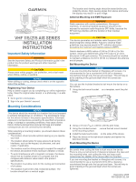
Important Safety Information
WARNING
See the
Important Safety and Product Information
guide in the
product box for product warnings and other important
information.
CAUTION
Always wear safety goggles, ear protection, and a dust mask
when drilling, cutting, or sanding.
NOTICE
When drilling or cutting, always check what is on the opposite
side of the surface.
Registering Your Device
Help us better support you by completing our online registration
today. Keep the original sales receipt, or a photocopy, in a safe
place.
1
Go to
garmin.com/express
.
2
Sign in to your Garmin
®
account.
Mounting Considerations
NOTICE
This device should be mounted in a location that is not exposed
to extreme temperatures or conditions. The temperature range
for this device is listed in the product specifications. Extended
exposure to temperatures exceeding the specified temperature
range, in storage or operating conditions, may cause device
failure. Extreme-temperature-induced damage and related
consequences are not covered by the warranty.
When selecting a mounting location, you should observe these
considerations.
•
The location should provide optimal viewing as you operate
your boat.
•
The location should allow for easy access to all device
interfaces, such as the keypad, touchscreen, and card
reader, if applicable.
•
The location must be strong enough to support the weight of
the device and protect it from excessive vibration or shock.
•
To avoid interference with a magnetic compass, the device
should not be installed closer to a compass than the
compass-safe distance value listed in the product
specifications.
•
The location must allow room for the routing and connection
of all cables.
•
The location must not be a flat, horizontal surface. The
location should be in a vertical angle.
The location and viewing angle should be tested before you
install the device. High viewing angles from above and below
the display may result in a poor image.
Antenna Mounting and EME Exposure
WARNING
Radio operators with cardiac pacemakers, life-support
machines, or electrical medical equipment should not be
exposed to excessive radio-frequency (RF) fields, because the
RF field may interfere with the function of their medical
equipment.
CAUTION
This device generates and radiates radio frequency (RF)
electromagnetic energy (EME). Failure to observe these
guidelines may expose people to RF radiation absorption
exceeding the maximum permissible exposure (MPE).
Garmin declares a MPE radius of 2.48 m (97.64 in.) for this
system, which was determined using 5 W output to an omni-
directional, 6 dBi gain antenna. The antenna should be installed
to maintain a distance of 2.48 m (97.64 in.) between the antenna
and all people.
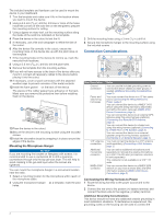
Bail Mounting the Device
NOTICE
If you are mounting the bracket on fiberglass with screws, it is
recommended to use a countersink bit to drill a clearance
counterbore through only the top gel-coat layer. This will help to
avoid cracking in the gel-coat layer when the screws are
tightened.
You can use the included bracket to bail mount the device on a
flat surface.
1
Using the bail-mount bracket
À
as a template, mark the pilot
holes.
2
Using a 3.5 mm (
9
/
64
in.) drill bit, drill the pilot holes.
3
Using the included screws
Á
, secure the bail-mount bracket
to the mounting surface.
4
Install the bail-mount knobs
Â
on the sides of the device.
5
Place the device in the bail-mount bracket and tighten the
bail-mount knobs.
Flush Mounting the Device
NOTICE
Be careful when cutting the hole to flush mount the device.
There is only a small amount of clearance between the case and
the mounting holes, and cutting the hole too large could
compromise the stability of the device after it is mounted.
If you are mounting the bracket on fiberglass with screws, it is
recommended to use a countersink bit to drill a clearance
counterbore through only the top gel-coat layer. This will help to
avoid cracking in the gel-coat layer when the screws are
tightened.
September 2018
190-02426-02_0A