Garmin VHF 115 Installation Instructions PDF - Page 2
Connection Considerations
 |
View all Garmin VHF 115 manuals
Add to My Manuals
Save this manual to your list of manuals |
Page 2 highlights
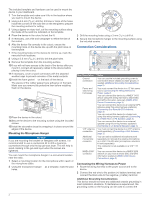
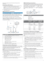
The included template and hardware can be used to mount the device in your dashboard. 1 Trim the template and make sure it fits in the location where you want to mount the device. 2 Using a 9.5 mm (3/8 in.) drill bit, drill one or more of the holes inside the corners of the solid line on the template to prepare the mounting surface for cutting. 3 Using a jigsaw or rotary tool, cut the mounting surface along the inside of the solid line indicated on the template. 4 Place the device in the cutout to test the fit. 5 If necessary, use a file and sandpaper to refine the size of the cutout. 6 After the device fits correctly in the cutout, ensure the mounting holes on the device line up with the pilot holes on the template. 7 If the mounting holes on the device do not line up, mark the new pilot-hole locations. 8 Using a 3.5 mm (9/64 in.) drill bit, drill the pilot holes. 9 Remove the template from the mounting surface. 10If you will not have access to the back of the device after you mount it, connect all necessary cables to the device before placing it into the cutout. 11If necessary, cover unused connectors with the attached weather caps to prevent corrosion of the metal contacts. 12Install the foam gasket on the back of the device. À The pieces of the rubber gasket have adhesive on the back. Make sure you remove the protective liner before installing them on the device. 13Place the device in the cutout. 14Secure the device to the mounting surface using the included screws . Á 15Install the decorative bezel by snapping it in place around the edges of the device. Mounting the Microphone Hanger NOTICE If you are mounting the bracket on fiberglass with screws, it is recommended to use a countersink bit to drill a clearance counterbore through only the top gel-coat layer. This will help to avoid cracking in the gel-coat layer when the screws are tightened. You can mount the microphone hanger in a convenient location near the radio. 1 Select a mounting location for the microphone within reach of the microphone cable. 2 Using the microphone hanger as a template, mark the pilot holes. À 3 Drill the mounting holes using a 3 mm (1/8 in.) drill bit. 4 Secure the microphone hanger to the mounting surface using the included screws . Á Connection Considerations Item Description Ground À connection Power and Á data wiring harnesses VHF antenna  connection Additional à microphone connector NMEA 2000® Ä connector Notes You can use the included grounding screw to connect the device chassis to water ground, if needed (Additional Grounding Considerations, page 2). You must connect the device to a 12 Vdc power source (Connecting the Wiring Harness to Power, page 2). You can connect this device to a NMEA® 0183 device using this wiring harness to share DSC and GPS information (optional) (NMEA 0183 Device Connections, page 3). You can connect this device to an external GPS antenna using this wiring harness (optional) (Connecting to a Remote GPS Antenna, page 3). You can connect this device to a hailer horn using this wiring harness (optional) (Connecting to a Hailer Horn or PA Speaker, page 3). You can connect this device to an external speaker using this wiring harness (optional) (Connecting to an External Speaker, page 3). You must connect the device to a VHF antenna (sold separately) (Connecting a VHF Antenna, page 3). You can add an additional microphone (sold separately) or relocate the existing microphone on a VHF 215 AIS radio (microphone relocation kit sold separately). This connector is not available on a VHF 115 radio. You can connect this device to a NMEA 2000 network on your boat to share DSC and GPS information (optional) (NMEA 2000 Device Connections, page 3). Connecting the Wiring Harness to Power 1 Route the wiring harness to the power source and to the device. 2 Connect the red wire to the positive (+) battery terminal, and connect the black wire to the negative (-) battery terminal. Additional Grounding Considerations This device should not need any additional chassis grounding in most installation situations. If interference is experienced, the grounding screw on the housing can be used to connect the 2
-
 1
1 -
 2
2 -
 3
3 -
 4
4
 |
 |
