Garmin VHF 115 Installation Instructions PDF - Page 3
Connecting to a Hailer Horn or PA Speaker - manual
 |
View all Garmin VHF 115 manuals
Add to My Manuals
Save this manual to your list of manuals |
Page 3 highlights
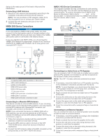
device to the water ground of the boat to help avoid the interference. Connecting a VHF Antenna 1 Mount the VHF antenna (sold separately) according to the installation instructions provided with the antenna. NOTE: You can purchase a VHF extension cable. Go to http://buy.garmin.com or contact your Garmin dealer. 2 Connect the VHF antenna to the port on the VHF 115/215 AIS device. NMEA 2000 Device Connections NOTICE If you are installing a NMEA 2000 power cable, you must connect it to the boat ignition switch or through another in-line switch. NMEA 2000 devices will drain your battery if the NMEA 2000 power cable is connected to the battery directly. If you are unfamiliar with NMEA 2000, you should read the "NMEA 2000 Network Fundamentals" chapter of the Technical Reference for NMEA 2000 Products. Go to www.garmin.com /manuals/VHF115-215 . NMEA 0183 Device Connections This diagram illustrates two-way connections for both sending and receiving data. You can also use this diagram for one-way communication. To receive information from a NMEA 0183 device on this device, refer to items , , , and in the ÊËÍ Î second table. To transmit information to a NMEA 0183 device from this device, refer to items , , , and in the second ÊËÏ Ð table. Item À Á Â Ã Item Ê Ë Ì Í Î Ï Ð Description Power source Power cable NMEA 0183 device NMEA 0183 cable Garmin Wire Function Power Power ground Not applicable RxA (+) RxB (-) TxA (+) TxB (-) Garmin Wire Color Red Black Not applicable Purple Gray Blue Brown NMEA 0183 Device Wire Function Power Power ground Data ground (if applicable) TxA (+) TxB (-) RxA (+) RxB (-) Item Description Compatible NMEA 2000 chartplotter or other device VHF 115/215 AIS device Ignition or in-line switch NMEA 2000 power cable NMEA 2000 drop cable 12 Vdc power source NMEA 2000 terminator or backbone cable NMEA 2000 T-connector NMEA 2000 terminator or backbone cable Connecting to a Remote GPS Antenna This device includes an internal GPS antenna. If your mounting location does not provide good GPS reception, you may install a remote GPS antenna with a female BNC connector (not included), and connect it to the device. NOTE: If you connected this device to a NMEA 2000 with a GPS antenna, you can use that antenna as a GPS source instead of installing a remote GPS antenna (NMEA 2000 Device Connections, page 3). 1 Follow the instructions provided with the external GPS antenna to install it on your boat correctly. 2 Route the GPS antenna cable to the back of the VHF 115/215 AIS device, away from sources of electrical interference. 3 Connect the GPS antenna cable to the BNC connector on the wiring harness on the VHF 115/215 AIS device. Connecting to a Hailer Horn or PA Speaker You can connect a VHF 215 AIS radio to a hailer horn or public address (PA) speaker (not included) to use the microphone or the handset to make announcements. NOTE: The VHF 115 radio cannot be connected to a hailer horn. 1 If necessary, mount the hailer horn or PA speaker according to the installation instructions provided with the device. NOTE: To avoid feedback, you should mount the hailer horn or PA speaker at least 3 m (10 ft) away from, and facing away from, the microphone or handset. 2 Route or extend the wire from the hailer horn or PA speaker to the radio. 3 Connect the white wire on the radio wiring harness to the positive (+) wire from the hailer horn or PA speaker. 4 Connect the green wire on the radio wiring harness to the negative (-) wire from the hailer horn or PA speaker. 5 Cover the connections with a waterproof tape or heat-shrink tubing. Connecting to an External Speaker You can connect the radio to an external speaker (not included) to hear the radio at a remote location. 1 If necessary, mount the speaker according to the installation instructions provided with the device. 2 Route or extend the wire from the speaker to the radio. 3 Connect the red wire on the radio wiring harness to the positive (+) wire from the speaker. 4 Connect the black wire on the radio wiring harness to the negative (-) wire from the speaker. 5 Cover the connections with a waterproof tape or heat-shrink tubing. 3
-
 1
1 -
 2
2 -
 3
3 -
 4
4
 |
 |
