Garmin VHF 215 AIS Installation Instructions
Garmin VHF 215 AIS Manual
 |
View all Garmin VHF 215 AIS manuals
Add to My Manuals
Save this manual to your list of manuals |
Garmin VHF 215 AIS manual content summary:
- Garmin VHF 215 AIS | Installation Instructions - Page 1
AIS SERIES INSTALLATION INSTRUCTIONS Important Safety Information WARNING See the Important Safety and Product Information guide in the product box card reader, if applicable. • The location must be strong enough to support the weight of the device and protect it from excessive vibration or shock. - Garmin VHF 215 AIS | Installation Instructions - Page 2
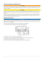
VHF Antenna Mounting and EME Exposure WARNING Radio operators with cardiac pacemakers, life-support machines, or electrical medical equipment should not be exposed to excessive radio-frequency (RF) fields, because the RF field may interfere with the function of - Garmin VHF 215 AIS | Installation Instructions - Page 3
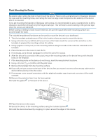
Flush Mounting the Device NOTICE Be careful when cutting the hole to flush mount the device. There is only a small amount of clearance between the case and the mounting holes, and cutting the hole too large could compromise the stability of the device after it is mounted. If you are mounting the - Garmin VHF 215 AIS | Installation Instructions - Page 4
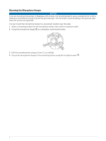
Mounting the Microphone Hanger NOTICE If you are mounting the bracket on fiberglass with screws, it is recommended to use a countersink bit to drill a clearance counterbore through only the top gel-coat layer. This will help to avoid cracking in the gel-coat layer when the screws are tightened. You - Garmin VHF 215 AIS | Installation Instructions - Page 5
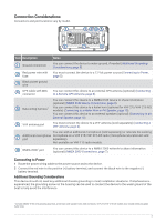
Connection Considerations Connectors and port locations vary by model. Item Description Notes Ground connection You can connect the device to water ground, if needed (Additional Grounding Considerations, page 5). Red power wire with fuse You must connect the device to a 12 Vdc power source ( - Garmin VHF 215 AIS | Installation Instructions - Page 6
Connecting a VHF Antenna 1 Mount the VHF antenna (sold separately) according to the installation instructions provided with the antenna. NOTE: You can purchase a VHF extension cable. Go to garmin.com or contact your Garmin dealer. 2 Connect the VHF antenna cable - Garmin VHF 215 AIS | Installation Instructions - Page 7
with NMEA 2000, you should read the "NMEA 2000 Network Fundamentals" chapter of the Technical Reference for NMEA 2000 Products. Go to garmin.com/manuals/nmea_2000. Item Description Compatible NMEA 2000 chartplotter or other device VHF 115/VHF 215/VHF 215 AIS device Ignition or in-line switch NMEA - Garmin VHF 215 AIS | Installation Instructions - Page 8
2000 with a GPS antenna, you can use that antenna as a GPS source instead of installing a remote GPS antenna (NMEA 2000 Connections, page 7). 1 Follow the instructions provided with the external GPS antenna to install it on your boat correctly. 2 Route the GPS antenna cable to the back of the VHF - Garmin VHF 215 AIS | Installation Instructions - Page 9
NMEA 0183 Device Connections This diagram illustrates two-way connections for both sending and receiving data. You can also use this diagram for one-way communication. The table below identifies the wiring harnesses and the NMEA 0183 wires. To receive information from a NMEA 0183 device, refer to - Garmin VHF 215 AIS | Installation Instructions - Page 10
install a hailer horn (optional) on the deck or tower of your boat. 1 If necessary, mount the hailer horn or PA speaker according to the installation instructions provided with the device. NOTE: To avoid feedback, you should mount the hailer horn or PA speaker at least 3 m (10 ft) away from, and - Garmin VHF 215 AIS | Installation Instructions - Page 11
Appendix Specifications Specification Dimensions (H x W x D) Weight Operating temperature range Storage temperature range Compass-safe distance Water rating Antenna connector Operating voltage Wireless frequency Standby current draw Receive current draw Transmit current draw Maximum antenna gain - Garmin VHF 215 AIS | Installation Instructions - Page 12
NMEA 2000 PGN Information Transmit PGN Description 059392 ISO acknowledgment 060928 ISO address claim 061184 Single-frame proprietary 126208 NMEA request group function 126464 PGN's group function 126720 Fast-packet proprietary 126993 Heartbeat 126996 Product information 126998 - Garmin VHF 215 AIS | Installation Instructions - Page 13
PGN 129041 129794 129798 129802 129809 129810 Description AIS Aids to Navigation (AtoN) report AIS class A static and voyage related data AIS SAR aircraft position report AIS safety related broadcast message AIS class B "CS" static data, part A AIS class B "CS" static data, part B NMEA 0183 - Garmin VHF 215 AIS | Installation Instructions - Page 14
© 2018 Garmin Ltd. or its subsidiaries support.garmin.com
-
 1
1 -
 2
2 -
 3
3 -
 4
4 -
 5
5 -
 6
6 -
 7
7 -
8
-
9
-
10
-
11
-
12
-
13
-
14
 |
 |
VHF
115/VHF
215/VHF
215
AIS
SERIES
INSTALLATION
INSTRUCTIONS
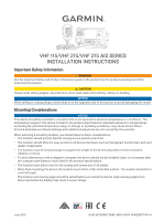
Important Safety Information
WARNING
See the
Important Safety and Product Information
guide in the product box for product warnings and other
important information.
CAUTION
Always wear safety goggles, ear protection, and a dust mask when drilling, cutting, or sanding.
NOTICE
When drilling or cutting, always check what is on the opposite side of the surface to avoid damaging the vessel.
Mounting Considerations
NOTICE
This device should be mounted in a location that is not exposed to extreme temperatures or conditions. The
temperature range for this device is listed in the product specifications. Extended exposure to temperatures
exceeding the specified temperature range, in storage or operating conditions, may cause device failure.
Extreme-temperature-induced damage and related consequences are not covered by the warranty.
When selecting a mounting location, you should observe these considerations.
•
The location should provide optimal viewing as you operate your boat.
•
The location should allow for easy access to all device interfaces, such as the keypad, touchscreen, and card
reader, if applicable.
•
The location must be strong enough to support the weight of the device and protect it from excessive
vibration or shock.
•
To avoid interference with a magnetic compass, the device should not be installed closer to a compass than
the compass-safe distance value listed in the product specifications.
•
The location must allow room for the routing and connection of all cables.
•
When flush mounting the device, the location must not be a flat, horizontal surface. The location should be in
a vertical angle.
The location and viewing angle should be tested before you install the device. High viewing angles from
above and below the display may result in a poor image.
GUID-4E35EBDF-6BB0-4B04-89C5-4642E8D77431 v4
June 2021