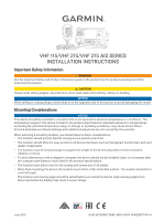
Garmin VHF 215 AIS Installation Instructions - Page 3
Flush Mounting the Device, NOTICE
 |
View all Garmin VHF 215 AIS manuals
Add to My Manuals
Save this manual to your list of manuals |
Page 3 highlights
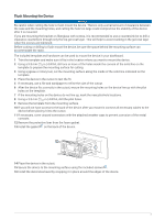
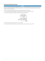
Flush Mounting the Device NOTICE Be careful when cutting the hole to flush mount the device. There is only a small amount of clearance between the case and the mounting holes, and cutting the hole too large could compromise the stability of the device after it is mounted. If you are mounting the bracket on fiberglass with screws, it is recommended to use a countersink bit to drill a clearance counterbore through only the top gel-coat layer. This will help to avoid cracking in the gel-coat layer when the screws are tightened. Before cutting or drilling to flush mount the device, be sure the space behind the mounting surface can accommodate the radio. The included template and hardware can be used to mount the device in your dashboard. 1 Trim the template and make sure it fits in the location where you want to mount the device. 2 Using a 9.5 mm (3/8 in.) drill bit, drill one or more of the holes inside the corners of the solid line on the template to prepare the mounting surface for cutting. 3 Using a jigsaw or rotary tool, cut the mounting surface along the inside of the solid line indicated on the template. 4 Place the device in the cutout to test the fit. 5 If necessary, use a file and sandpaper to refine the size of the cutout. 6 After the device fits correctly in the cutout, ensure the mounting holes on the device line up with the pilot holes on the template. 7 If the mounting holes on the device do not line up, mark the new pilot-hole locations. 8 Using a 3.5 mm (9/64 in.) drill bit, drill the pilot holes. 9 Remove the template from the mounting surface. 10 If you will not have access to the back of the device after you mount it, connect all necessary cables to the device before placing it into the cutout. 11 If necessary, cover unused connectors with the attached weather caps to prevent corrosion of the metal contacts. 12 Remove the protective liner from the foam gasket. 13 Install the gasket on the back of the device. 14 Place the device in the cutout. 15 Secure the device to the mounting surface using the included screws . 16 Install the decorative bezel by snapping it in place around the edges of the device. 3
-
 1
1 -
 2
2 -
 3
3 -
 4
4 -
 5
5 -
 6
6 -
 7
7 -
 8
8 -
 9
9 -
10
-
11
-
12
-
13
-
14
 |
 |
