Gateway MX6708 8511340 - Gateway Notebook Hardware Reference - Page 43
Tips & Tricks
 |
View all Gateway MX6708 manuals
Add to My Manuals
Save this manual to your list of manuals |
Page 43 highlights
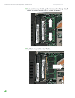
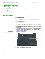
www.gateway.com Tips & Tricks The screw hole is marked with a K. Adding or replacing memory modules 5 Disconnect all peripheral devices connected to the notebook and remove any PC cards. 6 Turn your notebook over so the bottom is facing up, then remove the main battery and optional secondary battery. For more information, see "Changing batteries" on page 33. 7 Remove the keyboard screw. Screw 8 Loosen the six memory bay cover screws (these screws cannot be removed). Screws 9 Use the thumb notch to lift the memory bay cover, then remove it. Be careful not to break off the tabs located on the end of the cover opposite of the thumb notch. 39
-
 1
1 -
2
-
3
-
4
-
5
-
6
-
7
-
8
-
9
-
10
-
11
-
12
-
13
-
14
-
15
-
16
-
17
-
18
-
19
-
20
-
21
-
22
-
23
-
24
-
25
-
26
-
27
-
28
-
29
-
30
-
31
-
32
-
33
-
34
-
35
-
36
-
37
-
 38
38 -
 39
39 -
 40
40 -
 41
41 -
 42
42 -
 43
43 -
 44
44 -
 45
45 -
 46
46 -
 47
47 -
 48
48 -
49
-
50
-
51
-
52
-
53
-
54
-
55
-
56
-
57
-
58
-
59
-
60
-
61
-
62
-
63
-
64
-
65
-
66
-
67
-
68
-
69
-
70
-
71
-
72
 |
 |
Adding or replacing memory modules
www.gateway.com
39
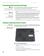
5
Disconnect all peripheral devices connected to the notebook and remove
any PC cards.
6
Turn your notebook over so the bottom is facing up, then remove the main
battery and optional secondary battery. For more information, see
“Changing batteries” on page 33
.
Tips & Tricks
The screw hole is marked with a K.
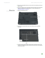
7
Remove the keyboard screw.
8
Loosen the six memory bay cover screws (these screws cannot be
removed).
9
Use the thumb notch to lift the memory bay cover, then remove it. Be
careful not to break off the tabs located on the end of the cover opposite
of the thumb notch.
Screw
Screws