GE 60-803-04 Installation Instructions - Page 1
GE 60-803-04 - Security Superbus 2000 LCD Alphanumeric Touchpad Manual
 |
UPC - 046188088645
View all GE 60-803-04 manuals
Add to My Manuals
Save this manual to your list of manuals |
Page 1 highlights
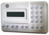
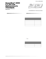
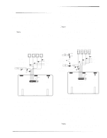
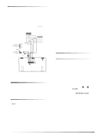
ITI Part No. 60-803 & 60-809 Document Number: 466-1632 Rev. B September 2000 Product Summary Installation Instructions Installation Guidelines The ITI® SuperBus 2000 2 x 20 LCD (liquid crystal display) Alphanumeric Touchpad gives you complete on-site system programming and operation control of a compatible security system (see the section "Specifications"). A two-line, 40-character display provides visual system status messages. The display identifies any programmed location, allowing the user to determine where an alarm, trouble, or open-sensor condition exists. Other features include: Touchpad buttons that light up after the first button press and remain lit until about 15 seconds after the last button press. Adjustable display contrast and backlighting. Built-in hardwire input (can be supervised with EOL resistor in SuperBus 2000 panels). Built-in door, which covers right-side buttons (60-809 only). SuperBus 2000 Panels vs. SuperBus Panels SuperBus 2000 panels assign module unit numbers automatically when the panel is powered up. This eliminates manually setting unit numbers and the chance of identical unit number conflicts. SuperBus 2000 Panels Advent Concord (software versions 2.0 and newer) Concord Express SuperBus panels communicate with SuperBus 2000 modules but require the module unit number to be set manually. Touchpads automatically default to unit number 001. SuperBus Panels UltraGard Concord (software versions 1.0-1.6) For the maximum number of bus devices and touchpads per panel see Table 1. Table 1: Maximum Bus Devices Per Panel Panel Maximum Bus Devices Advent 62 UltraGard 8 Concord 16 Concord Express 4 Do not exceed the total panel output power when using panel power for bus devices, touchpads, and hardwired sensors that require it (see specific panel Installation Instructions). Maximum current draw from the touchpad is 120 mA. Minimum current draw from the touchpad when the panel is operating only on backup battery is 15 mA. Mount the touchpad in an environmentally controlled area (32° to 140° F) (0° to 60° C). When using the optional touchpad hardwire input, use only shielded wire (22-gauge or larger), and do not exceed the maximum wire length limits in Table 2 between the touchpad and detection device. Note Shield wire must be connected to earth ground. Table 2. Hardwire Input Wire Length Limits Gauge Max. Wire Length 18 (shielded) 22 (shielded) 1000 Feet 350 Feet When mounting the touchpad back-plate, allow a 1inch clearance on all sides since the touchpad is larger than the back-plate. Use 4-conductor, 22-gauge or larger stranded wire from the touchpad to the control panel. Follow the wire length limits outlined in the specific panel Installation Instructions between the touchpad and control panel. SuperBus® 2000 2 x 20 LCD Alphanumeric Touchpad 1
-
 1
1 -
 2
2 -
 3
3 -
 4
4 -
 5
5 -
 6
6 -
 7
7 -
8
 |
 |