GE 60-803-04 Installation Instructions - Page 2
Tools Needed, Installation, Wiring - security
 |
UPC - 046188088645
View all GE 60-803-04 manuals
Add to My Manuals
Save this manual to your list of manuals |
Page 2 highlights
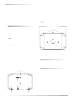
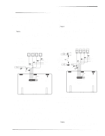
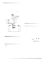
Tools Needed The following must be observed in UL installations The touchpad hardwire input must not be used for fire alarm initiating devices. Only UL-listed devices may be connected to the touchpad hardwire input. The touchpad hardwire input can be configured for normally closed or normally open protection devices. For UL installations with UltraGard and Concord (software versions 1.0-1.6) panels, do not use the touchpad hardwire input. Tools Needed Drill with bits Screwdrivers #6 screws and anchors (included) Panhead screws for a gang box installation Saw or utility knife for cutting wallboard To mount the touchpad in a gang box: 1. Separate the mounting bracket from the back-plate by loosening the two bottom screws and unlatching the tabs from the mounting slots (see Figure 1). 2. Line up the gang box mounting holes with the holes on the gang box (see Figure 2). 3. Secure the back-plate to the gang box with panhead screws. Note Do not overtighten screws or the back-plate may bind and prevent the touchpad from mounting properly. WALL MOUNTING HOLES (X4) BACK PLATE MOUNTING TABS (X3) Note Do not use screws larger than #6 or the touchpad will not seat properly onto the back-plate. Installation WIRE ACCESS HOLE The touchpad can be installed on a wall or in a gang box. To mount the touchpad on a wall: 1. Separate the mounting bracket from the back-plate by loosening the two bottom screws and unlatching the tabs from the mounting slots (see Figure 1). 2. Place the back-plate on the wall and mark the four mounting holes and the wire access hole (see Figure 2). Be sure to leave a 1-inch clearance on all sides of the back-plate. 3. Drill holes and insert appropriate anchors. 4. Secure the back-plate to the wall with included screws. 5. Cut a hole in the wall where the wire access hole was marked to pull your cable through. MOUNTING SLOTS OPENING FOR CONNECTOR CABLE OPENING GANG BOX MOUNTING HOLES (X2) 3101G02B.DS4 Figure 2. Back-Plate and Mounting Holes Wiring Wiring consists of connecting the touchpad wiring harness to the panel terminals. You may also connect an optional hardwire sensor to the touchpad hardwire input wires. Before You Begin 1. Disconnect the panel AC power transformer and backup battery (turn off power switch on UltraGard panels). 2. Run a 4-conductor, 22-gauge wire cable from the panel to the touchpad location. 3. Splice the 4-conductor cable wires to the matching colored wires located on the touchpad wiring harness. Find your panel in the next section for specific wiring instructions. LOOSEN BOTTOM SCREWS (X2) 3101G03B.DSF Figure 1. Touchpad Mounting Slots 2 SuperBus® 2000 2 x 20 LCD Alphanumeric Touchpad
-
 1
1 -
 2
2 -
 3
3 -
 4
4 -
 5
5 -
 6
6 -
 7
7 -
 8
8
 |
 |