GE GTH21KBXBB Use and Care Manual - Page 13
Icemaker Installation, CAUTION
 |
UPC - 084691176206
View all GE GTH21KBXBB manuals
Add to My Manuals
Save this manual to your list of manuals |
Page 13 highlights
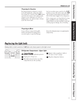
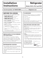
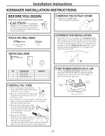
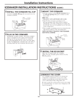
Installation Instructions ICEMAKER INSTALLATION INSTRUCTIONS BEFORE YOU BEGIN Read each step thoroughly before proceeding. • CAUTION - Unplug the Refrigerator. To eliminate the danger of electric shock during installation, you must unplug the refrigerator from its electrical outlet. TOOLS YOU WILL NEED Flat blade and Phillips screwdrivers Pliers PARTS INCLUDED 2 REMOVE THE OUTLET COVER • Remove the outlet cover with a flat-blade screwdriver. Side Back 3 PREPARE FOR INSTALLATION Inside the freezer, loosen the two mounting screws, but do not screw them all the way out. If your model does not have the screws already in the freezer wall, look for two plug buttons. Remove the plug buttons and insert the two Phillips head screws. The screws should extend approximately 1/2″ (13mm) out from the freezer wall. 1 Mounting screws 2 NO. DESCRIPTION 1 Water Fill Tube 2 Ice Fill Guide 3 Water Fill Tube Seal 3 QUANTITY 1 1 1 1 INSTALL FILL TUBE • If the refrigerator already has a water tube inlet on the back of the refrigerator, go to Step 2. • Remove and discard the white plug from the lower left back corner of the freezer wall. Remove plug • Go to the back of the refrigerator. Find the small label in the upper right hand corner and peel it off. Then discard the label. • Peel one side of the paper away Seal from the water fill tube seal, slide the seal along the tube and affix to the back side of the water tube inlet flange. • Remove the adhesive backing on the opposite side of the water fill tube seal and slide the tube into the hole near the top at the back of the refrigerator. Firmly press on the inlet to secure it to the refrigerator. 4 SET POWER SWITCH TO O (off) Set the icemaker power switch to O (off). Leave the power switch in the O (off) position until the refrigerator is connected to the water supply to prevent premature operation. Power Switch Hole for wire tie (Appearance may vary) 13
-
 1
1 -
2
-
3
-
4
-
5
-
6
-
7
-
 8
8 -
 9
9 -
 10
10 -
 11
11 -
 12
12 -
 13
13 -
 14
14 -
 15
15 -
 16
16 -
 17
17 -
 18
18 -
19
-
20
-
21
-
22
-
23
-
24
-
25
-
26
-
27
-
28
-
29
-
30
-
31
-
32
-
33
-
34
-
35
-
36
-
37
-
38
-
39
-
40
-
41
-
42
-
43
-
44
-
45
-
46
-
47
-
48
-
49
-
50
-
51
-
52
-
53
-
54
-
55
-
56
-
57
-
58
-
59
-
60
-
61
-
62
-
63
-
64
-
65
-
66
-
67
-
68
-
69
-
70
-
71
-
72
-
73
-
74
-
75
-
76
-
77
-
78
-
79
-
80
-
81
-
82
-
83
-
84
-
85
-
86
-
87
-
88
-
89
-
90
-
91
-
92
-
93
-
94
-
95
-
96
 |
 |
