GE GTX22EASKWW Installation Instructions
GE GTX22EASKWW Manual
 |
View all GE GTX22EASKWW manuals
Add to My Manuals
Save this manual to your list of manuals |
GE GTX22EASKWW manual content summary:
- GE GTX22EASKWW | Installation Instructions - Page 1
dryer is removed from service or discarded, remove the dryer door. • Service information and the wiring diagram are located in the control console. • Do not allow children on or in the appliance with the instructions found in "Connecting the Dryer to House Vent" later in this manual. Flexible vent - GE GTX22EASKWW | Installation Instructions - Page 2
Instructions harm. Gas appliances can dryer legs. Be sure to remove all of the foam pieces around the legs. Remove literature and bag containing accessories. ROUGH-IN 27 GE strongly recommends the use of factory specified parts. These hoses are manufactured and tested to meet GE specifications. GE - GE GTX22EASKWW | Installation Instructions - Page 3
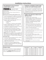
MAY REQUIRE GREATER THAN 0" OF REAR CLEARANCE. A 1" MINIMUM IS RECOMMENDED. Gas Dryers Only: • No other fuel burning appliance shall be installed in the same closet as a gas dryer. • The dryer must be disconnected from the gas supply piping during pressure testing at pressures greater than ½ psi - GE GTX22EASKWW | Installation Instructions - Page 4
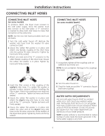
Installation Instructions CONNECTING INLET HOSES CONNECTING INLET HOSES (on some models) To produce steam, the dryer must connect to until firmly seated. 5. Ensure the rubber flat washer is in place and attach the dryer's long inlet hose to one male end of the ''Y'' connector. Tighten by hand until - GE GTX22EASKWW | Installation Instructions - Page 5
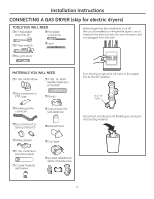
Installation Instructions CONNECTING A GAS DRYER (skip for electric dryers) TOOLS YOU WILL NEED ˆ10" Adjustable wrenches (2) ˆ Flat-blade screwdriver ˆ8" Pipe wrench ˆ Level Before beginning the installation, turn off the circuit breaker(s) or remove the dryer's circuit fuse(s) at the - GE GTX22EASKWW | Installation Instructions - Page 6
with a valve and burner assembly for use only with natural gas. Using conversion kit WE25X217, your local service organization can convert this dryer for use with propane (LP) gas. (To convert from propane (LP) to natural gas, conversion kit WE25X218 will be utilized.) ALL CONVERSIONS MUST BE - GE GTX22EASKWW | Installation Instructions - Page 7
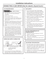
Installation Instructions CONNECTING THE DRYER TO THE GAS SUPPLY A Install a female 3/8" NPT elbow at the end of the dryer gas inlet. Install a 3/8" flare union adapter to the female elbow. IMPORTANT: Use a pipe wrench to securely hold on to the end of the dryer gas inlet to prevent twisting the - GE GTX22EASKWW | Installation Instructions - Page 8
Installation Instructions CONNECTING A GAS DRYER (skip for electric dryers) (cont.) TEST FOR LEAKS Never use an open flame to test for gas leaks. Check all connections for leaks with soapy solution or equivalent. Apply a soap solution. The leak test solution must not contain ammonia, which could - GE GTX22EASKWW | Installation Instructions - Page 9
Installation Instructions CONNECTING AN ELECTRIC DRYER (Skip for gas dryers and if your dryer already has a power cord attached) TOOLS YOU WILL NEED ˆSlip-joint pliers ˆPhillips screwdriver Before making the electrical connection, turn off the circuit breaker(s) or remove the dryer's circuit - GE GTX22EASKWW | Installation Instructions - Page 10
as to whether the appliance is properly grounded. DO NOT modify the plug on the power supply cord. If it will not fit the outlet, have a proper outlet installed by a qualified electrician. SAVE THESE INSTRUCTIONS ELECTRICAL CONNECTION INFORMATION FOR ELECTRIC DRYERS For direct wire connections - GE GTX22EASKWW | Installation Instructions - Page 11
Installation Instructions CONNECTING DRYER USING 4-WIRE CONNECTION (MUST BE USED FOR MOBILE HOME INSTALLATION) NOTE: Since January 1, 1996, the National Electrical Code requires that new constructions use a 4-wire connection to an electric dryer. A 4-wire cord must also be used where local codes - GE GTX22EASKWW | Installation Instructions - Page 12
exhaust length table. Failure to follow these instructions can result in death or fire. UL-LISTED FLEXIBLE METAL CLOTHES DRYER TRANSITION DUCT • If rigid metal cannot be used, then UL-LISTED flexible metal clothes dryer transition duct (GE parts - PM08X10085, WX08X10085 or WX08X10077) can be used - GE GTX22EASKWW | Installation Instructions - Page 13
Installation Instructions • DO cut duct as short as possible and install straight into wall. the energy cost. • Reduce the dryer life. • Accumulate lint, creating a potential fire hazard. The correct exhaust installation is YOUR RESPONSIBILITY. Problems due to incorrect installation are not covered - GE GTX22EASKWW | Installation Instructions - Page 14
Installation Instructions EXHAUSTING THE DRYER (cont.) EXHAUST SYSTEM CHECKLIST HOOD OR WALL CAP • Terminate be tight to avoid leaks. The male end of each section of duct must point away from the dryer. • Duct joints should be made air- and moisture-tight by wrapping the overlapped joints with duct - GE GTX22EASKWW | Installation Instructions - Page 15
Installation Instructions SIDE OR BOTTOM VENTING Dryer Exhaust to right of cabinet for Electric models only. Dryer Exhaust to left of cabinet for Gas and Electric models. Dryer Exhaust to the bottom of cabinet for Gas and Electric models. WARNING - Fire Hazard Close the back opening with cover - GE GTX22EASKWW | Installation Instructions - Page 16
Instructions EXHAUSTING THE DRYER (cont.) FINAL SETUP SIDE OR BOTTOM VENTING (cont.) ADDING ELBOW AND DUCT FOR EXHAUST TO LEFT OR RIGHT SIDE OF CABINET (cont.) • Apply duct tape as DUCT shown on the joint TAPE between the dryer from your local service provider. Place dryer in final location. - GE GTX22EASKWW | Installation Instructions - Page 17
instructions all the way through before starting. • Handle parts carefully to avoid scratching paint. • Set screws down by their related parts dryer from its electrical outlet A REVERSING THE DOOR - SOLID DOOR MODELS DOOR instructions A or B for your model. A REVERSING THE DOOR - SOLID DOOR MODELS - GE GTX22EASKWW | Installation Instructions - Page 18
Installation Instructions REVERSING THE DOOR (cont.) A REVERSING THE DOOR - SOLID DOOR MODELS (cont.) 5 Mount the door on the 2 upper To return the door to the original setup, follow these instructions, swapping "left" and "right". When you finish Plug the dryer back into its electrical outlet. 18 - GE GTX22EASKWW | Installation Instructions - Page 19
Instructions REVERSING THE DOOR B REVERSING THE DOOR - GLASS PANEL DOOR MODELS 1 Open the door approximately 130 degrees. With a putty knife, remove the 4 plastic caps located along the left side of the front panel and set them aside. Plastic Cap (4) B REVERSING THE DOOR - GLASS PANEL DOOR MODELS - GE GTX22EASKWW | Installation Instructions - Page 20
side here Plastic caps Inner door B REVERSING THE DOOR - GLASS PANEL DOOR MODELS (cont.) 8 Mount the assembled door on the 2 upper left side hinge screws the original setup, follow these instructions, swapping "left" and "right". When you finish Plug the dryer back into its electrical outlet. 20 - GE GTX22EASKWW | Installation Instructions - Page 21
ón Secadora 05 Si tiene alguna pregunta, llame a 800.GE.CARES (800.432.2737) o visite nuestro sitio Web las instrucciones de "Cómo conectar la secadora a la ventilación doméstica" de este manual. Los materiales de los conductos flexibles a menudo se desploman, se aplastan y atrapan pelusas - GE GTX22EASKWW | Installation Instructions - Page 22
reproductivos. Los electrodomésticos a gas puedan causar una exposición de patas. Saque la literatura y la bolsa que contiene la información. DIMENSIONES APROXIMADAS 27" (68,8 cm) Y Pie Cúbico X Y 6.2 43 3/8" 26 3/4" se cubran las especificaciones de GE. GE recomienda enfáticamente el uso de - GE GTX22EASKWW | Installation Instructions - Page 23
REQUERIR MAS DE 0" DE ESPACIO EN LA PARTE TRASERA. 1" (2.54 CM) MÍNIMO ES LA RECOMENDADA. Secadoras a Gas Únicamente: • No se deberá instalar ning sobre la conexión eléctrica, consulte la section. CABLES DE CORRIENTE: GE recomienda enfáticamente el uso de piezas específicas de fábrica. Seleccione - GE GTX22EASKWW | Installation Instructions - Page 24
goma se encuentre en su lugar y sujete el otro extremo de la manguera larga de entrada al conector de la válvula de llenado en la parte inferior del panel trasero de la secadora. Ajuste a mano hasta que esté firmemente asentada. 8. Abra el grifo de agua. 9. Controle la presencia de pérdidas - GE GTX22EASKWW | Installation Instructions - Page 25
de metal flexible de 4" diámetro (si fuese necesario) ˆ Compuesto o PTFE cinta para tuberías ˆGuantes ˆ Conector de tubería de gas flexible ˆSolución jabonosa para detección de pérdidas ˆ Abrazaderas de tubería (2) o abrazaderas de resorte (2) ˆ Campana de salida ˆGafas de seguridad ˆCinta - GE GTX22EASKWW | Installation Instructions - Page 26
CON CÓDIGOS LOCALES Y REQUERIMIENTOS DE ORDENANZAS. CONEXIÓN DE SUMINISTRO DE GAS DE LA SECADORA 1-7/8" 3-1/8" SUMINISTRO DE GAS ROSCA MACHO NPT DE 3/8" NOTA: Agregue a la dimensión vertical la distancia entre la parte inferior del gabinete y el piso. • Debe utilizar un conector flexible - GE GTX22EASKWW | Installation Instructions - Page 27
ón cónica en la toma a rosca. NOTA: Aplique compuesto para tubería o cinta PTFE a las roscas del adaptador y a la toma. Conector nuevo de línea de gas de metal flexible Adaptador Codo NPT de 3/8" Los productos que no suministrados Adaptador Tapón de tubería npt de 1/8" para controlar la presión de - GE GTX22EASKWW | Installation Instructions - Page 28
DE PÉRDIDAS Nunca utilice una llama abierta para detectar pérdidas de gas. Controle todas las conexiones con una solución jabonosa o un elemento no provisto), ajustando el mismo al tornillo conectado a tierra de color verde en la parte trasera de la secadora, y a una conexión cañería metálica de - GE GTX22EASKWW | Installation Instructions - Page 29
Instrucciones de instalación CÓMO CONECTAR UNA SECADORA ELECTRICA (Sáltese si se trata de las secadoras a gas o si su secadora ya tiene un cable de alimentación conectado) HERRAMIENTAS NECESARIAS ˆ Pinzas ˆ Destornillador Phillips ˆDestornillador de lados planos ˆ Nivel Antes de efectuar la - GE GTX22EASKWW | Installation Instructions - Page 30
Instrucciones de instalación CÓMO CONECTAR UNA SECADORA ELECTRICA (cont.) (Sáltese si se trata de las secadoras a gas o si su secadora ya tiene un cable de alimentación conectado) CONEXIÓN ELÉCTRICA INFORMACIÓN SOBRE LAS SECADORAS ELÉCTRICAS Para realizar conexiones eléctricas con - GE GTX22EASKWW | Installation Instructions - Page 31
la caja eléctrica. 2. Verifique que el cable de la secadora esté desenchufado del tomacorriente. 3. Quite la tapa del cable de energía ubicada en la parte trasera inferior. 4. Instale un alivio de tensión de 3/4 pulgadas reconocido por UL en el orificio de entrada del cable de energía. Pase el cable - GE GTX22EASKWW | Installation Instructions - Page 32
una chimenea, la salida de la cocina, ventilación de gas, pared, cielo raso, ático, espacio de rastreo, por UL puede ser utilizado. (GE partes - PM08X10085, WX08X10085 o WX08X10077.) transición que cumplan con "UL 2158A STANDARD FOR CLOTHES DRYER TRANSITION DUCT" (UL 2158A - Norma de conductos para - GE GTX22EASKWW | Installation Instructions - Page 33
la longitud permisible del sistema de escape. • En el cálculo de la longitud total del sistema de ventilación, debe agregar todas las partes rectas y codos del sistema (incluyendo el conducto de transición). LONGITUD DE ESCAPE LONGITUD MÁXIMA RECOMENDADA Tipos de campanas de escape Recomendado - GE GTX22EASKWW | Installation Instructions - Page 34
que la lavadora. Esto permitirá un acceso directo para poder efectuar la conexión de salida. Deslice el extremo del conducto de salida hacia la parte trasera de la secadora y sujete con cinta aislante o una abrazadera de mangueras. NOTA: Recomendamos el uso de un conducto de salida rígido de metal - GE GTX22EASKWW | Installation Instructions - Page 35
eléctricos. La secadora cuenta con una salida hacia la izquierda del gabinete en modelos a gas y eléctricos. La secadora cuenta con una salida por la parte inferior del gabinete en modelos a gas y eléctricos. ADVERTENCIA - Riesgo de incendio Cierre la abertura trasera con la placa protectora (Kit - GE GTX22EASKWW | Installation Instructions - Page 36
de la ubicación definitiva y ajuste las cuatro patas para garantizar que la secadora se encuentre nivelada de lado a lado y del frente a la parte trasera. Además ajuste las 2 patas antivuelco de las esquinas inferiores frontales, teniendo cuidado de que toquen el suelo para evitar la unidad vuelque - GE GTX22EASKWW | Installation Instructions - Page 37
Instrucciones de instalación INVERSIÓN DE LA PUERTA Cómo cambiar el sentido de apertura de la puerta. NOTAS IMPORTANTES: • Lea todas las instrucciones antes de comenzar. • Manipule las piezas con cuidado para evitar rayar la pintura. • Coloque los tornillos cercanos a sus piezas correspondientes - GE GTX22EASKWW | Installation Instructions - Page 38
Instrucciones de instalación INVERSIÓN DE LA PUERTA (cont.) A INVERSIÓN DE LA PUERTA - MODELOS DE PUERTA SÓLIDA (cont.) 5 Monte la puerta sobre los 2 tornillos superiores del lado izquierdo, instalados en el paso 2. Mueva los tornillos de la bisagra aflojados en el paso 3 hacia los agujeros - GE GTX22EASKWW | Installation Instructions - Page 39
Instrucciones de instalación INVERSIÓN DE LA PUERTA B INVERSIÓN DE LA PUERTA - MODELOS CON PANEL DE CRISTAL 1 Abra la puerta aproximadamente 130 grados. Con una espátula, retire las 4 tapas de plástico ubicadas a lo largo del lado izquierdo del panel frontal y deje las mismas a un costado. Tapa de - GE GTX22EASKWW | Installation Instructions - Page 40
Instrucciones de instalación INVERSIÓN DE LA PUERTA (cont.) B INVERSIÓN DE LA PUERTA - MODELOS CON PANEL DE CRISTAL (cont.) 6 Quite y cambie las 2 tapas de plástico y la bisagras de la puerta exterior. Instale las tapas de plástico de un lado opuesto aquí Instalar bisagras de lado opuesto aquí
-
 1
1 -
 2
2 -
 3
3 -
 4
4 -
 5
5 -
 6
6 -
 7
7 -
8
-
9
-
10
-
11
-
12
-
13
-
14
-
15
-
16
-
17
-
18
-
19
-
20
-
21
-
22
-
23
-
24
-
25
-
26
-
27
-
28
-
29
-
30
-
31
-
32
-
33
-
34
-
35
-
36
-
37
-
38
-
39
-
40
 |
 |
BEFORE YOU BEGIN
Read these instructions completely and carefully.
•
IMPORTANT
–
Save these instructions for local
electrical inspector’s use.
•
IMPORTANT
–
Observe all governing codes and
ordinances.
•
Install the clothes dryer according to the manufacturer’s
instructions and local codes.
•
Note to Installer –
Be sure to leave these instructions
with the Consumer.
•
Note to Consumer –
Keep these instructions for future
reference.
•
Clothes dryer installation must be performed by a
qualified installer.
•
This dryer
must
be exhausted to the outdoors.
•
Before the old dryer is removed from service or
discarded, remove the dryer door.
•
Service information and the wiring diagram are located
in the control console.
•
Do not allow children on or in the appliance. Close
supervision of children is necessary when the appliance
is used near children.
•
Proper installation is the responsibility of the installer.
•
Product failure due to improper installation is not
covered under the Warranty
.
•
Install the dryer where the temperature is above 50°F
for satisfactory operation of the dryer control system.
• Remove and discard existing plastic or metal foil duct
and replace with UL-listed duct.
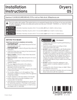
Questions? Call 800.GE.CARES (800.432.2737) or visit our Web site at: GEAppliances.com
- Fire Hazard
WARNING
•
Clothes dryer installation must be performed by a
qualified installer.
•
Install the clothes dryer according to these
instructions and local codes.
•
DO NOT
install a clothes dryer with flexible plastic
venting materials. If flexible metal (semi-rigid or
foil-type) duct is installed, it must be UL-listed and
installed in accordance with the instructions found
in “Connecting the Dryer to House Vent” later in
this manual. Flexible vent materials are known to
collapse, be easily crushed and trap lint. These
conditions will obstruct dryer airflow and increase
the risk of fire.
•
DO NOT
install or store this appliance in any
location where it could be exposed to water or
weather.
•
To reduce the risk of severe injury or death, follow
all installation instructions.
•
Save these instructions. (Installers: Be sure to leave
these instructions with the customer.)
Installation
Dryers
Instructions
05
This is the safety alert symbol. This symbol alerts you to potential hazards that can kill you or hurt you and others.
All safety messages will follow the safety alert symbol and the word “DANGER”, “WARNING”, or “CAUTION”. These
words are defined as:
Indicates a hazardous situation which, if not avoided,
will
result in death or serious injury.
Indicates a hazardous situation which, if not avoided,
could
result in death or serious injury.
Indicates a hazardous situation which, if not avoided,
could
result in minor or moderate injury.
DANGER
WARNING
CAUTION
31-16775
10-15
GE
Printed in Mexico
234D2318P005