GE PGS968SEPSS Installation Instructions - Page 2
Caution, Warning - appliance
 |
UPC - 084691199755
View all GE PGS968SEPSS manuals
Add to My Manuals
Save this manual to your list of manuals |
Page 2 highlights
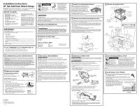
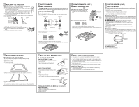
9 REPLACING THE OVEN DOOR NOTE: The oven door is heavy. You may need help lifting the door high enough to slide it into the hinge slots. Do not lift the door by the handle. A. Lift the oven door by placing one hand on each side. The door is heavy, so you may need help. Do not lift the door by the handle. B. With the door at the same angle as the removal position (approximately 1"-2" [2.5 cm-5.1 cm] from the closed position), seat the notch of the hinge arm into the bottom edge of the hinge slot. The notch of the hinge arm must be fully seated into the bottom of the slot. C. Fully open the door. If the door will not fully open, the indentation is not seated correctly in the bottom edge of the slot. D. Push the hinge locks up against the front frame of the oven cavity, to the locked position. E. Close the oven door. Hinge in locked position Bottom edge of slot Hinge arm Notch of hinge securely fitted into bottom of hinge slot Hinge notch REPLACE THE STORAGE DRAWER A. Place the drawer rail on the guides. Push the drawer in until it stops. B. Lift the front of the drawer and push in until the stops clear the guides. C. Lower the front of the drawer and push in until it closes. Stop 10 COOKTOP BURNERS ASSEMBLE THE BURNERS CAUTION: The electrode of the spark igniter is exposed. Be careful not to impact the electrode, as damage to the igniter could occur. Be careful not to turn on any cooktop controls while touching an electrode. A slight electrical shock may occur. If you have a glass ceramic cooktop, skip to B . A FOR METAL COOKTOPS A. Place burner heads over the electrodes on the cooktop, in the correct locations according to their sizes. Medium head and cap Small head and cap Large head and cap Front of range Large head and cap B. Make sure the slot in the burner head is positioned over the electrode (on some models). C. Place the matching size caps onto the heads. Burner cap Burner cap not properly seated properly seated Make sure that the heads and caps are placed in the correct locations. Place the vent cover, grates and air inlet cover onto the cooktop, making sure that the grates lock the vent cover in place. Vent cover 10 COOKTOP BURNERS (CONT.) ASSEMBLE THE BURNERS (CONT.) If you have a metal cooktop, skip to C . B FOR GLASS CERAMIC COOKTOPS A. Place burner heads over the electrodes on the cooktop, in the correct locations according to their sizes. Burner grate B. Place the matching size caps onto the heads. Burner cap Burner head Burner base Spark igniter Spark igniter location Burner cap Burner cap not properly seated properly seated Make sure that the heads and caps are placed in the correct locations. Place the vent cover, grates and air inlet cover onto the cooktop, making sure that the grates lock the vent cover in place. Vent cover 10 COOKTOP BURNERS (CONT.) C CHECK THE IGNITERS Operation of the electric igniters should be checked after the cooktop and supply line have been carefully checked for leaks and the cooktop has been connected to the electrical power. A. Turn on gas. B. Push and turn a burner valve to the LITE position. • The burner valve should light when gas is available to the burner. • Once the burner lights, it should be turned out of the LITE position. C. Try each valve separately until all burners have been checked. D BURNER IGNITION Cooktop Spark Ignition-When you turn the cooktop knob to LITE, the spark igniter makes a series of electric sparks (ticking sounds) which light the burner. During a power failure, the burners will not light automatically. In an emergency, a cooktop burner may be lit with a match by following the steps below. WARNING: Lighting gas burners with a match is dangerous. You should match light the cooktop burners only in an emergency. A. Light a match and hold the flame near the burner you want to light. Wooden matches work best. B. Push in and turn the control knob slowly. Be sure you are turning the correct knob for the burner you are lighting. NOTE: If the burner does not light within 5 seconds, turn the knob off and wait 5 minutes before trying again. E BURNER FLAMES Turn each burner on. Turn each burner knob to the high position. Flames should be blue in color with little or no trace of yellow. The burner flames should not flutter or blow away from the burner. The inner cone of the flame should be between 1/2" and 3/4" (12.7 mm and 19.1 mm) long. If the burner flames are yellow in color or not the proper length, call GE Service. 1/2" to 3/4" (12.7 mm to 19.1 mm) COOKTOP BURNER Flames should circle burner Burners should be checked frequently. WARNING: If you attempt to measure the inner cone of the flame, please use caution. Burns could result. 11 BAKE AND BROIL BURNERS A CHECKING THE OVEN BURNERS To check the bake burner flames with the oven door in the closed position: A. Open the door and remove it. (Optional-see Step 4.) B. Remove the oven racks. C. Remove the oven bottom. Lift the oven bottom up at the rear and pull forward. D. Remove the four screws holding the burner baffle (flame spreader) to the burner box. E. Install and close the oven door. F. Turn on the bake burner. The broil burner flames may be seen without removing the racks, oven bottom or bake baffles. 11 BAKE AND BROIL BURNERS (CONT.) B ADJUST THE AIR SHUTTER WHAT ADJUSTMENT TO MAKE: A. If the flames are yellow, open the air shutter more than the original setting. B. If the flames blow away or flutter from the burner, close the air shutter more than the original setting. Air shutter opening Air shAuitrteSr ahdujutstment sAcrdejwustment MAKING THE ADJUSTMENT: A. Bake burner: Remove the orifice fitting cover. The broil burner is located and accessible in the top rear of the oven. Orifice fitting cover B. Using a screwdriver, loosen the air shutter adjustment screw. C. Make the air shutter adjustment. D. Retighten the air shutter screw. Air shutter screw Air shutter E. Check the inner cone of the flame. It should be between 1/2" and 3/4" (12.7 mm and 19.1 mm) long for the oven bake and broil burners. Inner cone CoOf fNlaODmEINLeTLEARMIOAR 1/2" to 3/4" (12.7 mm to1/129" .T1Om3/m4") OQvUeEnMAbDroOilRerPARA bHuOrnReNrEAR/ASAR 12 FINAL INSTALLATION CHECKLIST • Check to make sure the circuit breaker is closed (RESET) or the circuit fuses are replaced. • Be sure power is in service to the building. • Check that all packing materials and tape have been removed. This will include tape on metal panel under control knobs (if applicable), adhesive tape, wire ties, cardboard and protective plastic. Failure to remove these materials could result in damage to the appliance once the appliance has been turned on and surfaces have heated. • Check that the door and drawer are parallel to each other and that both operate smoothly. If they do not, repeat steps 4 and 9. • Check to make sure that the rear leveling leg is fully inserted into the anti-tip bracket and that the bracket is securely installed. OPERATION CHECKLIST • Check that the oven control operates properly. If the oven control does not operate properly, recheck the wiring connections. • Be sure all range controls are in the OFF position before leaving the range. WHEN ALL ADJUSTMENTS ARE MADE AND THE RESULTS ARE SATISFACTORY: A. Replace the orifice fitting cover. B. Replace the burner baffle (flame spreader) and screws. C. Replace the oven bottom. D. Replace the oven door.
-
 1
1 -
 2
2
 |
 |
