Gigabyte B560M POWER User Manual - Page 16
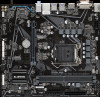
M2P_CPU, M2A_SB M.2 Socket 3 Connectors, F_AUDIO Front Panel Audio Header
 |
View all Gigabyte B560M POWER manuals
Add to My Manuals
Save this manual to your list of manuals |
Page 16 highlights
B B_ S F_ S_ _F _3 U 8) M2P_CPU (Note)/M2A_SB (M.2 Socket 3 Connectors) The M.2 connector suppo_ r0ts M.F2 SATA SSDs or M.2 PCIe SSDs. M2P_CPU (Note) 60 80 80 60 M2A_SB _0 F Follow the steps below to correctly install an M.2 SSD in the M.2 connector. Step 1: Locate the proper mounting hole for the M.2 SSD to be installed and then install the mounting clip first. Step 2: Slide the M.2 SSD in_t3o the coUnnector at an angle. Step 3: Press the M.2 SSD down and then secure it by pressing the clip pin into the mounting hole. Select the proper hole for the mounting clip according to the length of the M.2 SSD to be installed. _ S_ (Note) Supported by 11th Generation processors only. _ _B F_USB3 F 3 S S F _0 _F B _ _U 9) F_AUDIO (Front Panel Audio Header) The front panel audio header supports High Definition audio (HD). You may connect your chassis front panel audio module to this header. Make sure the wire assignments of the module connector match the pin assignments of the motherboard header. Incorrect connection between the module connector and the motherboard header will make the device unable to work or even damage it. _S S_ _ B Pin No. Definition Pin No. Definition 9 1 10 2 1 MIC2_L 2 GND 6 Sense 7 FAUDIO_JD 3 MIC2_R 8 No Pin 4 NC 9 LINE2_L 5 LINE2_R 10 Sense S B_ B Some chassis provide a front panel audio module that has separated connectors on each wire instead of a single plug. For information about connecting the front panel audio module that has different wire assignments, please contact the chassis manufacturer. B B _ B S_ - 16 -
-
 1
1 -
2
-
3
-
4
-
5
-
6
-
7
-
8
-
9
-
10
-
 11
11 -
 12
12 -
 13
13 -
 14
14 -
 15
15 -
 16
16 -
 17
17 -
 18
18 -
 19
19 -
 20
20 -
 21
21 -
22
-
23
-
24
-
25
-
26
-
27
-
28
-
29
-
30
-
31
-
32
-
33
-
34
-
35
-
36
-
37
-
38
-
39
-
40
-
41
-
42
-
43
 |
 |
