Gigabyte B560M POWER User Manual - Page 17
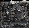
F_PANEL Front Panel Header, SPI_TPM Trusted Platform Module Header, SPEAK, PLED/PWR_LED
 |
View all Gigabyte B560M POWER manuals
Add to My Manuals
Save this manual to your list of manuals |
Page 17 highlights
SS U F_ 12345 1 23 1 1 23 1 SS 1 S 1 23 1 23 1 10) F_PANEL (Front Panel Header) Connect the power switch, reset switch, speaker, chassis intrusion switch/sensor and system status indicator on the chassis to this header according to the pin assignments below. Note the positive and negative pins before connecting the cables. _ F_ B S B_ B Power LED Power Switch Speaker PLED+ PLED- PW+ PWSPEAK+ NC NC SPEAK- 2 20 1 19 HD+ HD- RESRES+ CICI+ PWR_LED+ PWR_LEDPWR_LED- Hard Drive Reset Activity LED Switch Power LED Chassis Intrusion Header •• PLED/PWR_LED (Power LED): System Status LED S0 On S3/S4/S5 Off B S_ •• PWBF(_Power Switch): Connects to the power status indicator on the chassis front panel. The LED is on when the system is operating. The LED is off when the system is in S3/S4 sleep state or powered off (S5). S S U 12345 Connects to the power switch on the chassis front panel. You may configure the way to turn off your system using the power switch (refer to Chapter 2, "BIOS Setup," "Settings\Platform Power," for more information). •• SPEAK (Speaker): Connects to the speaker on the chassis front panel. The sSystem reports system startup status by issuing a beep code. One singSle short beep will be heard if no problem is detected at system startup. •• HD (Hard Drive Activity LED): _ S Connects to the hard drive activity LED on the chassis front panel. The LED is on when the hard drive is reading or writing data. S_ _S_B •• RES (Reset Switch): Connects to the reset switch on the chassis front panel. Press the reset switch to restart the computer if the computer freezes and fails to perform a normal restart. •• CI (Chassis Intrusion Header): _ B S_ _ U Connects to the chassis intrusion switchB/sensor on the chassis that can detect if theBchassis cover has _ been removed. This function requires a chassis with aF chassis intrusion switch/sensor. B •• NC: No connection. F_USB3 F The front panel design may differ by chassis. A front panel module mainly consists of power switch, reset front switch, power panel module tLoEtDhi,shhaerdadderSirv,Bem_BaackteivistyurLeEtDh,eswpeiraekaesrsaignndmeetcn.tsWahnedn connecting your chassis the pin assignments are matched correctly. _0 11) SPI_TPM (Trusted Platform Module Header) _ YouSm_ay connect an SPI TPM (Trusted Pl_atfSorm Module) to this header. S_ _ B Pin No. Definition _F Pin No. Definition 11 1 1 Data Output 7 Chip Select 12 2 2 Power (_3.U3V) 8 GND U __ 3 3 No Pin_ 4 NC B 9 IRQ 10 NC F 5 Data Input _ 101 F NC 6 CFL_KUSB3 F 12 RST _ _0 S F_ _ _B - 17 - _ S_ _ B_ _F
-
 1
1 -
2
-
3
-
4
-
5
-
6
-
7
-
8
-
9
-
10
-
11
-
 12
12 -
 13
13 -
 14
14 -
 15
15 -
 16
16 -
 17
17 -
 18
18 -
 19
19 -
 20
20 -
 21
21 -
 22
22 -
23
-
24
-
25
-
26
-
27
-
28
-
29
-
30
-
31
-
32
-
33
-
34
-
35
-
36
-
37
-
38
-
39
-
40
-
41
-
42
-
43
 |
 |
