Gigabyte B660M AORUS PRO AX DDR4 User Manual - Page 23
CPU_OPT Water Cooling CPU Fan Header, LED_C1/LED_C2 RGB LED Strip Headers, Connector, CPU_FAN
 |
View all Gigabyte B660M AORUS PRO AX DDR4 manuals
Add to My Manuals
Save this manual to your list of manuals |
Page 23 highlights
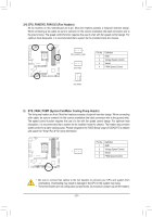
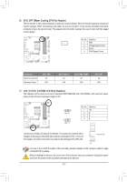
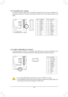
6) CPU_OPT (Water Cooling CPU Fan Header) The fan header is 4-pin and possesses a foolproof insertion design. Most fan headers possess a foolproof insertion design. When connecting a fan cable, be sure to connect it in the correct orientation (the black connector wire is the ground wire). The speed control function requires the use of a fan with fan speed control design. Pin No. Definition 1 1 GND 2 Voltage Speed Control 3 Sense 4 PWM Speed Control Connector Maximum Current Maximum Power CPU_FAN 2A 24W SYS_FAN1~3 2A 24W SYS_FAN4_PUMP 2A 24W CPU_OPT 2A 24W 7) LED_C1/LED_C2 (RGB LED Strip Headers) The headers can be used to connect a stDaEnBdUaGrd 5050 RGB LED strip (12V/G/R/B), with maximum power rating of 2A (12V) and maximum length oPfO2RmT . DEBUG PORT 1 LED_C2 1 LED_C1 Pin No. 1 2 3 4 Definition 12V G R B Connect your RGB LED strip to the header. The power pin (marked with a triangle on the plug) of the LED strip must be connected to Pin 1 (12V) of this header. Incorrect connection may lead to the damage of the LED strip. RGB LED Strip 1 12V For how to turn on/off the lights of the LED strip, please navigate to the "Unique Features" page of GIGABYTE's website. Before installing the devices, be sure to turn off the devices and your computer. Unplug the power cord from the power outlet to prevent damage to the devices. - 23 -
-
 1
1 -
2
-
3
-
4
-
5
-
6
-
7
-
8
-
9
-
10
-
11
-
12
-
13
-
14
-
15
-
16
-
17
-
 18
18 -
 19
19 -
 20
20 -
 21
21 -
 22
22 -
 23
23 -
 24
24 -
 25
25 -
 26
26 -
 27
27 -
 28
28 -
29
-
30
-
31
-
32
-
33
-
34
-
35
-
36
-
37
-
38
-
39
-
40
-
41
-
42
-
43
-
44
 |
 |
