Gigabyte G1.Assassin Manual - Page 22
Back Panel Connectors
 |
UPC - 818313012203
View all Gigabyte G1.Assassin manuals
Add to My Manuals
Save this manual to your list of manuals |
Page 22 highlights
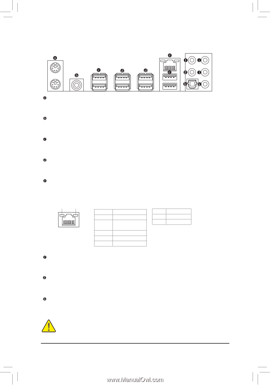
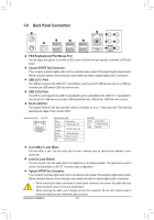
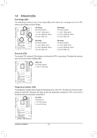
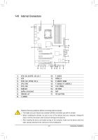
1-8 Back Panel Connectors PS/2 Keyboard and PS/2 Mouse Port Use the upper port (green) to connect a PS/2 mouse and the lower port (purple) to connect a PS/2 keyboard. Coaxial S/PDIF Out Connector This connector provides digital audio out to an external audio system that supports digital coaxial audio. Before using this feature, ensure that your audio system provides a coaxial digital audio in connector. USB 2.0/1.1 Port The USB port supports the USB 2.0/1.1 specification. Use this port for USB devices such as a USB keyboard/mouse, USB printer, USB flash drive and etc. USB 3.0/2.0 Port The USB 3.0 port supports the USB 3.0 specification and is compatible to the USB 2.0/1.1 specification. Use this port for USB devices such as a USB keyboard/mouse, USB printer, USB flash drive and etc. RJ-45 LAN Port The Gigabit Ethernet LAN port provides Internet connection at up to 1 Gbps data rate. The following describes the states of the LAN port LEDs. Speed/Activity LED Link LED LAN Port Speed/Activity LED: State Orange Green + Orange Description 10 Mbps data rate 100 Mbps data rate Green Blinking Off 1 Gbps data rate Network activity No connection Link LED: State Description On Linked properly Off No link Line In/Mic In Jack (Blue) The line in/Mic in jack. Use this audio jack for line in devices such as optical drive, walkman, microphone, etc. Line Out Jack (Green) The line out jack. Use this audio jack for a headphone or 2-channel speaker. This jack can be used to connect front speakers in a 4/5.1/7.1-channel audio configuration. Optical S/PDIF Out Connector This connector provides digital audio out to an external audio system that supports digital optical audio. Before using this feature, ensure that your audio system provides an optical digital audio in connector. • When removing the cable connected to a back panel connector, first remove the cable from your device and then remove it from the motherboard. • When removing the cable, pull it straight out from the connector. Do not rock it side to side to prevent an electrical short inside the cable connector. Hardware Installation - 22 -
-
 1
1 -
2
-
3
-
4
-
5
-
6
-
7
-
8
-
9
-
10
-
11
-
12
-
13
-
14
-
15
-
16
-
 17
17 -
 18
18 -
 19
19 -
 20
20 -
 21
21 -
 22
22 -
 23
23 -
 24
24 -
 25
25 -
 26
26 -
 27
27 -
28
-
29
-
30
-
31
-
32
-
33
-
34
-
35
-
36
-
37
-
38
-
39
-
40
-
41
-
42
-
43
-
44
-
45
-
46
-
47
-
48
-
49
-
50
-
51
-
52
-
53
-
54
-
55
-
56
-
57
-
58
-
59
-
60
-
61
-
62
-
63
-
64
-
65
-
66
-
67
-
68
-
69
-
70
-
71
-
72
-
73
-
74
-
75
-
76
-
77
-
78
-
79
-
80
-
81
-
82
-
83
-
84
-
85
-
86
-
87
-
88
-
89
-
90
-
91
-
92
-
93
-
94
-
95
-
96
-
97
-
98
-
99
-
100
-
101
-
102
-
103
-
104
-
105
-
106
-
107
-
108
-
109
-
110
-
111
-
112
-
113
-
114
-
115
-
116
-
117
-
118
-
119
-
120
-
121
-
122
-
123
-
124
-
125
-
126
-
127
-
128
 |
 |