Gigabyte GA-2AIEL5-RH Manual
Gigabyte GA-2AIEL5-RH Manual
 |
View all Gigabyte GA-2AIEL5-RH manuals
Add to My Manuals
Save this manual to your list of manuals |
Gigabyte GA-2AIEL5-RH manual content summary:
- Gigabyte GA-2AIEL5-RH | Manual - Page 1
GA-2AIEL1-RH GA-2AIEL5-RH AMD® mini-ITX Motherboard USER'S MANUAL AMD® mini-ITX Motherboard Rev. 1001 * The WEEE marking on the product indicates this product must not be disposed of with user's other household waste - Gigabyte GA-2AIEL5-RH | Manual - Page 2
GA-2AIEL1-RH/GA-2AIEL5-RH Motherboard Copyright © 2009 GIGA-BYTE TECHNOLOGY CO., LTD. All rights reserved. The trademarks mentioned in the manual are legally registered to their respective companies. Notice The written content provided with this product is the property of Gigabyte. No part of this - Gigabyte GA-2AIEL5-RH | Manual - Page 3
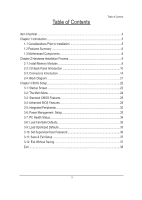
English Table of Contents Table of Content Item Checklist...4 Chapter 1 Introduction...5 1-1 Considerations Prior to Installation 5 1.2 Features Summary 6 1.3 Motherboard Components 8 Chapter 2 Hardware Installation Process 9 2-1: Install Memory Modules 9 2-2: I/O Back Panel Introduction 10 - Gigabyte GA-2AIEL5-RH | Manual - Page 4
GA-2AIEL1-RH/GA-2AIEL5-RH Motherboard Item Checklist The GA-2AIEL1-RH/GA-2AIEL5-RH motherboard Serial ATA cable x 2 I/O Shield Kit CD for motherboard driver & utility GA-2AIEL1-RH/GA-2AIEL5-RH Quick Reference Guide * The items listed above are for reference only, and are subject - Gigabyte GA-2AIEL5-RH | Manual - Page 5
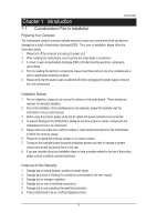
installation, please follow the instructions below: 1. Please turn off the information in the provided manual. 3. Before using the about any installation steps or have a problem related to the use of the product the conditions recommended in the user manual. 3. Damage due to improper installation - Gigabyte GA-2AIEL5-RH | Manual - Page 6
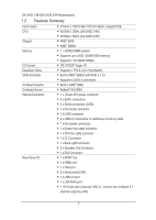
GA-2AIEL1-RH/GA-2AIEL5-RH Motherboard 1.2 Features Summary Form Factor 170mm x 170mm Mini ITX form factor, 4 layers PCB. CPU K8 BGA 1.0GHz (GA-2AIEL1-RH) K8 BGA 1.5GHz (GA-2AIEL5-RH) Chipset AMD® 690E AMD® SB600 Memory 1 x DDR2 DIMM sockets Supports up to 2GB 533/ - Gigabyte GA-2AIEL5-RH | Manual - Page 7
Introduction Enhanced features with CPU Vcore, DDR2 1.8V , +3.3V, +12V value viewing System/CPU temperature value viewing CPU shutdown when overheat Realtek RTL8111C GbE coneroller Supports WOL Award BIOS on 8Mb SPI Flash ROM Supports S1, S3, S4, S5 under Windows Operating System - Gigabyte GA-2AIEL5-RH | Manual - Page 8
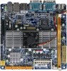
F_USB1 F_PANEL F_USB2 DIO_CON GA-2AIEL1-RH/GA-2AIEL5-RH Motherboard 1.3 Motherboard Components (GA-2AIEL1-RH/GA-2AIEL5-RH) SYS_FAN1 CF Card connector SATA 1 SATA 2 SATA 3 SATA 4 AMD SB600 ATX Power DDRll_1 CLR_CMOS1 BATTERY CPU AMD 690E ITE Super I/O LVDS_CON BLIGHT_CON1 COM2 VGA COM1 - Gigabyte GA-2AIEL5-RH | Manual - Page 9
the socket until the retaining clips snap back in place. Reverse the installation steps if you want to remove the DIMM module. Table 1. Supported DIMM Module Type Size 256MB 512MB 1GB 2GB Organization 8MB x 8 x 4 bks 16MB x 16 x 4bks 16MB x 8 x 4bks 132MB x 16 x 4bks 32MB x 8 x 4bks 64MB - Gigabyte GA-2AIEL5-RH | Manual - Page 10
GA-2AIEL1-RH/GA-2AIEL5-RH Motherboard 2-2: I/O Back Panel Introduction 10 - Gigabyte GA-2AIEL5-RH | Manual - Page 11
device(s) such as USB keyboard, mouse, scanner, zip, speaker...etc. have a standard USB interface. Also make sure your OS supports USB controller. If your OS does not support USB controller,please contact OS vendor for possible patch or driver updated. For more information please contact your OS - Gigabyte GA-2AIEL5-RH | Manual - Page 12
GA-2AIEL1-RH/GA-2AIEL5-RH Motherboard NOTE: After installing the HDMI device, make sure the VGA output connect to D-SUB/HDMI under Advanced BIOS Features. Please note the HDMI audio output only supports AC3, DTS and 2-channel-LPCM formats. (AC3 and DTS require the use of an external decoder - Gigabyte GA-2AIEL5-RH | Manual - Page 13
Hardware Installation Process Line In The default Line In jack. Devices like CD-ROM, walkman etc. can be connected to Line In jack. Line Out (Front Speaker Out) The default Line Out (Front Speaker Out) jack. Stereo speakers, earphone or front surround speakers can be connected to Line Out (Front - Gigabyte GA-2AIEL5-RH | Manual - Page 14
GA-2AIEL1-RH/GA-2AIEL5-RH Motherboard 2-3: Connectors Introduction 34 32 35 7 8 9 10 11 1 2 3 13 14 1 2 20 33 29 28 6 31 27 17 30 25 26 24 36 16 19 18 4 5 - Gigabyte GA-2AIEL5-RH | Manual - Page 15
20-pin ATX power connectors Connector Introduction With the use of the power connector, the power supply can supply enough stable power to all the components on the motherboard. Before connecting the power connector, please make sure that all components and devices are properly installed. Align - Gigabyte GA-2AIEL5-RH | Manual - Page 16
GA-2AIEL1-RH/GA-2AIEL5-RH Motherboard SATAII0_1~4 (Serial ATA cable connectors) F_SAUADTIOA 3Gb/s can provide up to 300MB/s stransfer rate. Please refer to the BIOS setting for the SATA 3Gb/s - Gigabyte GA-2AIEL5-RH | Manual - Page 17
is the same as the pin assigment on the MB header. To find out if the chFa_AsUsDisIOyou areMbOuDyEiMng support front audio connSemcatortrC,aprdleRaeasder contact DPVRM your dealer. F_PANEL F1_1394 F_PANEL F_AUDIO 91 SPDIF_IO 10 2 Pin No. 1 2 3 4 5 6 7 8 9 10 - Gigabyte GA-2AIEL5-RH | Manual - Page 18
GA-2AIEL1-RH/GA-2AIEL5-RH Motherboard LVDS connector LVDS stands for Low-voltage differential signaling, which uses high-speed analog circuit techniques to provide multigigabit data transfers on copper interconnects - Gigabyte GA-2AIEL5-RH | Manual - Page 19
connector and possesses a foolproof connection design. Most coolers are designed with color-coded power connector wires. A red power connector wire indicates a positive connection and requires a +12V power voltage. The black connector wire is the ground wire (GND). Remember to connect the CPU/system - Gigabyte GA-2AIEL5-RH | Manual - Page 20
GA-2AIEL1-RH/GA-2AIEL5-RH Motherboard BATTERY F_USB F_1394 Serial ATA F1_1394 CAUTION Danger of explosion if battery is incorrectly replaced. SPDIF Replace only with the same or equivalent type - Gigabyte GA-2AIEL5-RH | Manual - Page 21
2-4: Block Diagram Clock Generator ICS951464AS Block Diagram CPU AMD BGA Unbuffered 400/533/667/800 DDR2 DIMM HyperTransport Link HDMI PCI-E x4 slot 1X VGA Connector RGB 1 x PCI-E Interface Gigabit LAN Realtek RTL8111C USB x 8 SPI ROM USB 2.0 SPI I/F NB AMD 690E I2C I/F BOOTSTRAPS ROM - Gigabyte GA-2AIEL5-RH | Manual - Page 22
GA-2AIEL1-RH/GA-2AIEL5-RH Setup program. To upgrade the BIOS, use either the GIGABYTE Q-Flash or @BIOS utility. • Q-Flash allows the Internet and updates the BIOS. For instructions on using the Q-Flash and @BIOS potentially risky, if you do not encounter problems using the current version of BIOS, it - Gigabyte GA-2AIEL5-RH | Manual - Page 23
Inc. GA-2AIEL-RH F1 . . . . : BIOS Setup/Q-Flash : XpressRecovery2 : Boot Menu : Qflash 04/27/2007-RS690G-SB600-6A669G02C-00 BIOS Setup Function Key Press the key to show the BIOS POST screen. To show the BIOS POST screen at system startup, refer to the instructions - Gigabyte GA-2AIEL5-RH | Manual - Page 24
GA-2AIEL1-RH/GA-2AIEL5-RH Motherboard 3-2 The Main Menu Once you enter the BIOS Setup program, the Main Menu (as shown below) appears on the screen. Use arrow keys to - Gigabyte GA-2AIEL5-RH | Manual - Page 25
BIOS Setup Standard CMOS Features Use this menu to configure the system time and date, hard drive types, floppy disk drive types, and the type of errors that stop the system boot, etc. Advanced BIOS Features Use this menu to configure the device boot order, advanced features available on the CPU - Gigabyte GA-2AIEL5-RH | Manual - Page 26
GA-2AIEL1-RH/GA-2AIEL5-RH Motherboard 3-3 Standard CMOS Features CMOS Setup Utility-Copyright (C) skip the detection of the device during the POST for faster system startup. • Manual Allows you to manually enter the specifications of the hard drive when the hard drive access mode is - Gigabyte GA-2AIEL5-RH | Manual - Page 27
BIOS Setup The following fields display your hard drive specifications. If you wish to enter the parameters manually, refer to the information on the hard drive. Capacity Approximate capacity of the currently installed hard drive. Cylinder Number of cylinders. Head Number of heads. - Gigabyte GA-2AIEL5-RH | Manual - Page 28
GA-2AIEL1-RH/GA-2AIEL5-RH Motherboard 3-4 Advanced BIOS Features CMOS Setup Utility-Copyright (C) 1984-2007 Award Software Advanced BIOS Features AMD K8 Cool&Quiet control Hard Disk Boot Priority First - Gigabyte GA-2AIEL5-RH | Manual - Page 29
BIOS Setup Away Mode Enables or disables Away Mode in Windows XP Media Center operating system. Away Mode allows the system to silently perform unattended tasks while in a low-power mode that appears off (Default: Disabled) Internal Graphics Mode Auto Outputs from the onboard VGA if no PCI - Gigabyte GA-2AIEL5-RH | Manual - Page 30
GA-2AIEL1-RH/GA-2AIEL5-RH Motherboard 3-5 Integrated Peripherals CMOS Setup Utility-Copyright (C) 1984-2007 Award Dog Timer Select OnChip USB Controller USB EHCI Controller USB Keyboard Support USB Mouse Support Legacy USB storage detect Onboard Serial Port 1 Onboard Serial Port - Gigabyte GA-2AIEL5-RH | Manual - Page 31
that cannot be shared with other device. Set this option to Legacy IDE if you wish to install operating systems that do not support Native mode, e.g. Windows 9X/ME SATA ->AHCI Configures the SATA controller to AHCI mode. Advanced Host Controller Interface (AHCI) is an interface - Gigabyte GA-2AIEL5-RH | Manual - Page 32
GA-2AIEL1-RH/GA-2AIEL5-RH Motherboard 3-6 Power Management Setup CMOS Setup Utility-Copyright (C) 1984-2007 Award Software Power Management Setup ACPI Suspend Type Soft-Off by Power button USB Wake Up from S3 HPET Support (Note) Power On By Mouse Power On By Keyboard x KB Power ON - Gigabyte GA-2AIEL5-RH | Manual - Page 33
BIOS Setup HPET Support (Note) Enables or disables High Precision Event Timer (HPET) for Windows® Vista® operating system. (Default: Enabled) Power from the operating system or removal of the AC power, or the settings may not be effective. (Note) Supported on Windows® Vista® operating system only. 33 - Gigabyte GA-2AIEL5-RH | Manual - Page 34
GA-2AIEL1-RH/GA-2AIEL5-RH Motherboard 3-7 PC Health Status CMOS Setup Utility-Copyright (C) 1984-2007 Award Software PC Health Status Vcore DDR2 1.8V +3.3V +12V Current System Temperature Current CPU - Gigabyte GA-2AIEL5-RH | Manual - Page 35
3-8 Load Fail-Safe Defaults CMOS Setup Utility-Copyright (C) 1984-2007 Award Software Standard CMOS Features Load Fail-Safe Defaults Advanced BIOS Features Load Optimized Defaults Integrated Peripherals Set Supervisor Password Power Management Setup Set User Password PnP/PCI - Gigabyte GA-2AIEL5-RH | Manual - Page 36
GA-2AIEL1-RH/GA-2AIEL5-RH Motherboard 3-10 Set Supervisor/User Password CMOS Setup Utility-Copyright (C) 1984-2007 Award Software Standard CMOS Features Advanced BIOS Features Integrated Peripherals Power Management Setup - Gigabyte GA-2AIEL5-RH | Manual - Page 37
3-11 Save & Exit Setup CMOS Setup Utility-Copyright (C) 1984-2007 Award Software Standard CMOS Features Load Fail-Safe Defaults Advanced BIOS Features Load Optimized Defaults Integrated Peripherals Power Management Setup Set Supervisor Password Save to CMOS and EXIT (YSe/Nt U)?seYr - Gigabyte GA-2AIEL5-RH | Manual - Page 38
GA-2AIEL1-RH/GA-2AIEL5-RH Motherboard 38
-
 1
1 -
 2
2 -
 3
3 -
 4
4 -
 5
5 -
 6
6 -
 7
7 -
8
-
9
-
10
-
11
-
12
-
13
-
14
-
15
-
16
-
17
-
18
-
19
-
20
-
21
-
22
-
23
-
24
-
25
-
26
-
27
-
28
-
29
-
30
-
31
-
32
-
33
-
34
-
35
-
36
-
37
-
38
 |
 |

USER’S MANUAL
GA-2AIEL1-RH
GA-2AIEL5-RH
AMD
®
mini-ITX Motherboard
AMD
®
mini-ITX Motherboard
Rev. 1001
*
The WEEE marking on the product indicates this product must not be disposed of with user's
other household waste and must be handed over to a designated collection point for the
recycling of waste electrical and electronic equipment!!
*
The WEEE marking applies only in European Union's member states.