Gigabyte GA-2AIEL5-RH Manual - Page 14
: Connectors Introduction
 |
View all Gigabyte GA-2AIEL5-RH manuals
Add to My Manuals
Save this manual to your list of manuals |
Page 14 highlights
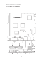
GA-2AIEL1-RH/GA-2AIEL5-RH Motherboard 2-3: Connectors Introduction 34 32 35 7 8 9 10 11 1 2 3 13 14 1 2 20 33 29 28 6 31 27 17 30 25 26 24 36 16 19 18 4 5 23 22 21 15 1. CPU Processor socket 19. BATTERY CMOS Battery 2. U1 AMD 690E 20. DDRII_1 DDR2 socket 3. U2 AMD SB600 21. AUDIO1 Audio port 4. LU3 Realtek RTL8111C GbE LAN controlle 22. R_USB USB 2.0 ports 5. CU1 Realtek ALC889A Audio controller 23. LAN Gigabit LAN port 6. U10 ITE IT8720F Super I/O controller 24. HDMI HDMI port 7. SATAII0_1 SATA Data cable connector 25. COM1 Serial port 8. SATAII0_2 SATA Data cable connector 26. OPTICAL S/PDIF port (Optical) 9. SATAII0_3 SATA Data cable connector 27. COM2/VGA Serial port and VGA port 10. SATAII0_4 SATA Data cable connector 28. COM3 Serial port cable connector 11. F_USB1 Front USB cable connector 29. COM4 Serial port cable connector 12. F_USB2 Front USB cable connector 30. JP6 Power COM select 13. F_PANEL Front panel connector 31. JP8 Power COM select 14. DIO_CON GPIO Input/Output connector 32. CF_CON CF connector 15. F_AUDIO1 Front HDA Audio cable connector 33. CPU_FAN1 CPU fan cable connector 16. BLIGHT_CON1 LVDS panel control connector 34. SYS_FAN1 System fan cable connector 17. LVDS_CON LVDS connector 35. ATX 20-pin ATX power connector 18. PCIEX4 PCI-E x4 slot (Gen2, x1 bandwidth) 36. CLR_CMOS1 Clear CMOS jumper Close:Clear CMOS Open:Normal CMOS setting (Default) 14
-
 1
1 -
2
-
3
-
4
-
5
-
6
-
7
-
8
-
 9
9 -
 10
10 -
 11
11 -
 12
12 -
 13
13 -
 14
14 -
 15
15 -
 16
16 -
 17
17 -
 18
18 -
 19
19 -
20
-
21
-
22
-
23
-
24
-
25
-
26
-
27
-
28
-
29
-
30
-
31
-
32
-
33
-
34
-
35
-
36
-
37
-
38
 |
 |
