Gigabyte GA-2AIEL5-RH Manual - Page 17
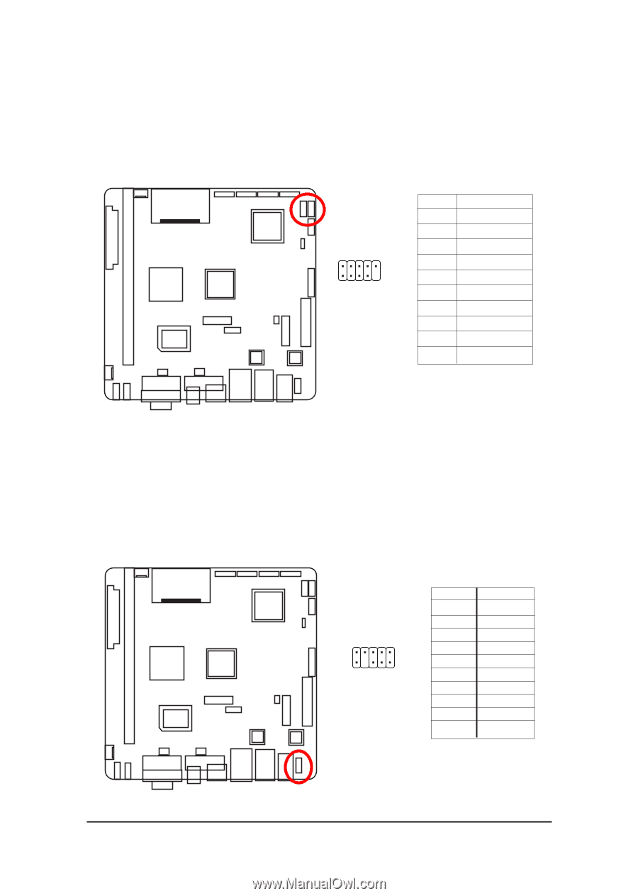
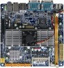
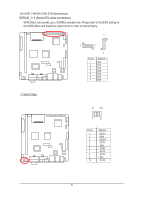
F_USB1/2 Front USB cable connectors, F_AUDIO1 Front AUDIO connector
 |
View all Gigabyte GA-2AIEL5-RH manuals
Add to My Manuals
Save this manual to your list of manuals |
Page 17 highlights
F_PANEL F_1394 IR/CIR F_USB1/2 (Front USB cable connectors) Connector Introduction F_PANEL Be careful with the polarity of the front USB connector. Check the pin assignment carefully while you connect the front USB cable, incorrect connection between the cable and connector will make the device unable to work or even damage it. For optional front USB cable, please contact your local dealer. IR COMB PWR_LED CLR_CMOS BIOS_WP CLR_CMOS BIOS_WP 2 10 F_USB 19 SUR_CEN Pin No. 1 2 3 4 5 6 7 8 9 10 Definition Power (5V) Power (5V) USB DxUSB DyUSB Dx+ USB Dy+ GND GND No Pin NC COMB FCI_AUDIO1 (Front AUDIO connector) Power If you want to use Front Audio connector, you must remove 5-6, 9-10 Jumper. In order to CLR_PWD utilize the front audio header, your chassis must have front audio connector. Also please F_PANEL make sure the pin assigment on the cable is the same as the pin assigment on the MB header. To find out if the chFa_AsUsDisIOyou areMbOuDyEiMng support front audio connSemcatortrC,aprdleRaeasder contact DPVRM your dealer. F_PANEL F1_1394 F_PANEL F_AUDIO 91 SPDIF_IO 10 2 Pin No. 1 2 3 4 5 6 7 8 9 10 Definition MIC_L GND MIC_R -ACZ_DEC Line_R F2_1394 GND Faudio_JD No Pin FL_iUneS_BL F_G1N39D4 GAME F_PANEL IR/CIR 17 IR SMB_CONN F_AUDIO (NEW)
-
 1
1 -
2
-
3
-
4
-
5
-
6
-
7
-
8
-
9
-
10
-
11
-
 12
12 -
 13
13 -
 14
14 -
 15
15 -
 16
16 -
 17
17 -
 18
18 -
 19
19 -
 20
20 -
 21
21 -
 22
22 -
23
-
24
-
25
-
26
-
27
-
28
-
29
-
30
-
31
-
32
-
33
-
34
-
35
-
36
-
37
-
38
 |
 |