Gigabyte GA-6LXSV Manual - Page 8
LAN4 Active LED Left
 |
View all Gigabyte GA-6LXSV manuals
Add to My Manuals
Save this manual to your list of manuals |
Page 8 highlights
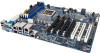
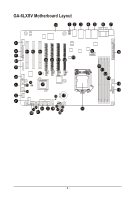
35 SATA_DOM1 36 J_HDA_SDO1 37 U7 38 F_USB1 39 BP_1 40 SGPIO 41 LAN3/LAN4 42 FP_1 43 COM2 44 PCI_1 45 PCI_2 46 PCI_3 47 IPMB1 48 PCIE_1 49 PCIE_2 50 BMC_LED2 51 PCIE_3 52 PCIE_4 53 CPU0_FAN1 SATA port 0 DOM support jumper. ME recovery jumper Intel C224 Chipest USB 2.0 header Back plane board header SGPIO header LAN3 Active LED (Right) LAN4 Active LED (Left) Front panel header Serial port cable connector PCI 32bit/33MHz slot PCI 32bit/33MHz slot PCI 32bit/33MHz slot IPMB connector PCI-E x16 slot (Shared bandwidth with PCIE_2/ PCIE_3 slot) PCI-E x16 slot (Shared bandwidth with PCIE_1/ PCIE_3 slot) BMC readiness LED PCI-E x16 slot (Shared bandwidth with PCIE_1/ PCIE_2 slot) PCI-E x16 slot (running at x1 mode) CPU fan connector CAUTION! If a SATA type hard drive is connected to the motherboard, please ensure the jumper is closed and set to 2-3 pins (Default setting), in order to reduce any risk of hard disk damage. Please refer to Page 31 for SATA_DOM1 and SATA_DOM2 jumper setting instruction. - 8 -
-
 1
1 -
2
-
 3
3 -
 4
4 -
 5
5 -
 6
6 -
 7
7 -
 8
8 -
 9
9 -
 10
10 -
 11
11 -
 12
12 -
 13
13 -
14
-
15
-
16
-
17
-
18
-
19
-
20
-
21
-
22
-
23
-
24
-
25
-
26
-
27
-
28
-
29
-
30
-
31
-
32
-
33
-
34
-
35
-
36
-
37
-
38
-
39
-
40
-
41
-
42
-
43
-
44
-
45
-
46
-
47
-
48
-
49
-
50
-
51
-
52
-
53
-
54
-
55
-
56
-
57
-
58
-
59
-
60
-
61
-
62
-
63
-
64
-
65
-
66
-
67
-
68
-
69
-
70
-
71
-
72
-
73
-
74
-
75
-
76
-
77
-
78
-
79
-
80
-
81
-
82
-
83
-
84
-
85
-
86
-
87
-
88
-
89
-
90
-
91
-
92
-
93
-
94
-
95
-
96
-
97
 |
 |
