Gigabyte GA-6TXSL Manual
Gigabyte GA-6TXSL Manual
 |
View all Gigabyte GA-6TXSL manuals
Add to My Manuals
Save this manual to your list of manuals |
Gigabyte GA-6TXSL manual content summary:
- Gigabyte GA-6TXSL | Manual - Page 1
GA-6TXSL-RH Intel® Core i7 Series Processor Motherboard USER'S MANUAL Intel® CoreTM2 Quad processorMotherboard Rev. 1001 * The WEEE marking on the product indicates this product must not be disposed of with user's other household waste - Gigabyte GA-6TXSL | Manual - Page 2
English GA-6TXSL-RH Motherboard Copyright © 2009 GIGA-BYTE TECHNOLOGY CO., LTD. All rights reserved. The trademarks mentioned in the manual are legally registered to their respective companies. Notice The written content provided with this product is the property of Gigabyte. No part of this manual - Gigabyte GA-6TXSL | Manual - Page 3
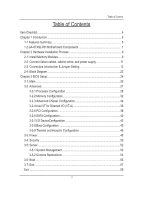
English Table of Contents Table of Content Item Checklist...4 Chapter 1 Introduction...5 1-1 Features Summary 5 1.2 GA-6TXSL-RH Motherboard Components 7 Chapter 2 Hardware Installation Process 9 2-1: Install Memory Modules 9 2-2: Connect ribbon cables, cabinet wires, and power supply 11 2-3: - Gigabyte GA-6TXSL | Manual - Page 4
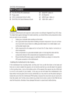
English GA-6TXSL-RH Motherboard Item Checklist The GA-6TXSL-RH motherboard Floppy cable CD for motherboard driver & utility GA-6TXSL-RH Quick Reference Guide Serial ATA cable x 6 I/O Shield Kit SATA Power cable x 6 USB+1394 cable x 1 WARNING! Computer motherboards and - Gigabyte GA-6TXSL | Manual - Page 5
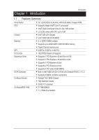
QPI I/O Control Expansion Slots SATA Controller On-Board Sound On-BoardIEEE 1934 12" x 9.6"(3.5cm X 24.4cm) ATX form factor, 6 layers PCB. Supports single Intel® Core i7 processor Intel® Dual Core/Quad Core in LGA 1366 socket L3 cache varies with CPU up to 12M Intel® X58 - Gigabyte GA-6TXSL | Manual - Page 6
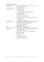
English GA-6TXSL-RH Motherboard On-Board LAN On-Board Peripherals Hardware Monitor BIOS Additional Features Intel® 82567LM GbE controller Supports WOL, PXE 1 x Floppy connector 2 x PS/2 connectors 1 x Parallel port supports Normal/EPP/ECP mode 2 x Serial - Gigabyte GA-6TXSL | Manual - Page 7
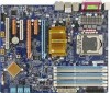
1.2 GA-6TXSL-RH Motherboard Components Introduction 1. CPU 2. Intel X58 ICH 3. Intel 82801IJR ICH10R 4. ITE IT 8720 5. PCIE x 16 Slot 6. PCIE x 4 Slot 7. PCIE x 16 Slot(@x8) 8. PCIE x 8 Slot 9. PCIE x 4 - Gigabyte GA-6TXSL | Manual - Page 8
English GA-6TXSL-RH Motherboard 28 1 37 35 36 27 29 30 31 32 33 34 46 2 24 25 26 23 22 3 4 21 11 20 12 19 5 6 7 8 9 10 42 13 16 18 39 40 41 14 15 17 38 8 - Gigabyte GA-6TXSL | Manual - Page 9
Installation Process GA-6TXSL-RH has 6 triple inline memory module (DIMM) sokcets. It supports Triple Channels Technology. The BIOS will automatically detects memory type and size during system boot. For detail DIMM installation, please refer to the following instructions. Channel 3 Channel - Gigabyte GA-6TXSL | Manual - Page 10
English GA-6TXSL-RH Motherboard Table 1. Supported DIMM Module Type Dual Channel Memory Configurations Table DDR3_2 DDR3_1 DDR3_4 DDR3_3 DDR3_6 DDR3_5 Two M odules - - DS/SS - - DS/SS - - - - Four M odules DS/SS DS/ - Gigabyte GA-6TXSL | Manual - Page 11
Hardware Installation Process 2-2: Connect ribbon cables, cabinet wires, and power supply 2-2-1 : I/O Back Panel Introduction 11 - Gigabyte GA-6TXSL | Manual - Page 12
English GA-6TXSL-RH Motherboard 2-3: Connectors Introduction & Jumper Setting 3 1 456 16 18 17 11 19 14 2 15 10 9 12 13 8 20 7 1. 24pin ATX power connector 2. 4pin 12V ATX power - Gigabyte GA-6TXSL | Manual - Page 13
Secure Gigital / Memory Stick Serial ATA SPDIF AUX_IN CD_IN Connector Introduction 1) ATX1 (Auxuliary Power Connector) AC power cord should only be connected to your power supply unit after ATX power cable and other related devices are firmly connected to the mainboard. PIN No. 1 Definition - Gigabyte GA-6TXSL | Manual - Page 14
English GA-6TXSL-RH Motherboard 3 ) FDD (Floppy Connector) ATX_12V Please connect the floppy drive ribbon cables to FDD. It supports 720K,1.2M,1.44M and 2.88Mbytes floppy disk types. The red stripe of the ribbon cable must be the same side with the Pin1. FDD 2 34 1 33 IDE 14 - Gigabyte GA-6TXSL | Manual - Page 15
on the cable is the same as the pin assigment on the MB header. To find out if the chassis you are buying support front audio connector, please contact your dealer. NB_FAN 12 Pin No. Definition WOL 1 MIC_L 2 GND 3 MIC_RI IDE 4 DETECT 5 FrontAudio(R) er 6 RearAudio - Gigabyte GA-6TXSL | Manual - Page 16
English GA-6TXSL-RH Motherboard 8 ) F_USB1 (Internal USB cable connector) Be careful with the polarity of the front USB connector. Check the pin assignment carefully while you connect the - Gigabyte GA-6TXSL | Manual - Page 17
10 ) 1394 (IEEE 1394 cable connectors) Connector Introduction 12 9 10 Pin No. 1 2 3 4 5 6 7 8 9 10 Definition TPA 1+ TPA 1GND GND TPB 1+ TPB 1BUS VCC BUS VCC No Pin GND 11 ) PWR_LED(System Power LED Header) This header can be used to connect a system power LED on the chasis to indicate system - Gigabyte GA-6TXSL | Manual - Page 18
English GA-6TXSL-RH Motherboard 12 ) F_Panel (2X10 Pins Front Panel connector) Please connect the power LED, PC speaker, reset switch and power switch of your chassis front panel - Gigabyte GA-6TXSL | Manual - Page 19
is incorrectly replaced. Replace only with the same or equivalent type recommended by the manufacturer. Dispose of used batteries according to the manufacturer's instructions. If you want to erase CMOS... 1.Turn OFF the computer and unplug the power cord.F1_1394 2.Remove the battery, wait for 30 - Gigabyte GA-6TXSL | Manual - Page 20
English GA-6TXSL-RH Motherboard 15 ) REAR_FAN (Front Fan and Rear fan cable connectors) This connector allows you to link with the cooling fan on the system case to - Gigabyte GA-6TXSL | Manual - Page 21
17 ) JP2 (Skip password jumper) Connector Introduction 1 1-2 Close: Normal operation (Default setting) 1 2-3 Close: Skip Supervisor Password inBIOS setup menu 18 ) JP3 (BIOS recovery jumper) 1 1-2 Close: Normal operation (Default setting) 1 2-3 Close: Enable BIOS Recovery mode 21 - Gigabyte GA-6TXSL | Manual - Page 22
English GA-6TXSL-RH Motherboard 19 ) JP1 (Clear CMOS jumper) You may clear the CMOS Close: Clear CMOS 20 ) SPDIF (SPDIF connector for RCA) This header supports digital S/PDIF in and can connect to an audio device that supports digital audio out via an optional S/PDIF in cable. For purchasing the - Gigabyte GA-6TXSL | Manual - Page 23
2-4: Block Diagram Block Diagram CLOCK GENERATOR CK505 INTEL LGA1366 core i7 1333/1066/800 VID0~5 VRD 11.1 PCI-E Graphic Card PCIE x16 Slot PCIE x4 Slot PCIE x8 Slot PCIE x8 Slot PCIE x16 PCIE x4 PCIE x8 PCIE x8 FSB IOH Intel X58 CHANNEL A DDR3 1066/1333 un-Buffered ECC/Non ECC/Reg ECC D/ - Gigabyte GA-6TXSL | Manual - Page 24
English GA-6TXSL-RH Motherboard Chapter 3 BIOS Setup BIOS (Basic Input and Output System) includes a CMOS SETUP utility which allows user to configure required settings or to activate certain - Gigabyte GA-6TXSL | Manual - Page 25
BIOS Setup GETTING HELP Main Menu The on-line description of the highlighted setup function is displayed at the bottom of the screen. Status Page Setup Menu / Option Page Setup Menu Press F1 to pop up a small help window that describes the appropriate keys to use and the possible selections for the - Gigabyte GA-6TXSL | Manual - Page 26
English GA-6TXSL-RH Motherboard 3-1 Main Once you enter Phoenix BIOS Setup Utility, the Main Menu (Figure 1) will appear on the screen. Use arrow keys to select among the - Gigabyte GA-6TXSL | Manual - Page 27
3-2 Advanced BIOS Setup 27 - Gigabyte GA-6TXSL | Manual - Page 28
English GA-6TXSL-RH Motherboard Processor Configuration 28 - Gigabyte GA-6TXSL | Manual - Page 29
multiprocessor(MP) specification revision level.ome operating system will require 1.1 for compatibility reasons. 1.4 Support MPS Version 1.4 . (Default setting) 1.1 Support M PS Version 1.1. Intel (R) Virtualization Technology Intel(R) Virtualization Technology will allow a platform to - Gigabyte GA-6TXSL | Manual - Page 30
English GA-6TXSL-RH Motherboard Enabled Adjacent Cache Line Prefetch. (Default setting) Disabled Disables this Disable Intel Hyper Threading Technology. A20M Support Enabled Enable A20M Support. (Default setting) Disabled Disable A20M Support. Machine Checking Enabled Enable Machine - Gigabyte GA-6TXSL | Manual - Page 31
BIOS Setup Set Max Ext CPUID=3 Enabled Enable Set Max Ext CPUID=3. Disabled Disable Set Max Ext CPUID=3. (Default setting) Echo TPR Enabled Enable Echo TPR. Disabled Disable Echo TPR.(Default setting) Discrete MTRR Allocation Enabled Enable Discrete MTRR Allocation. Disabled Disable - Gigabyte GA-6TXSL | Manual - Page 32
English GA-6TXSL-RH Motherboard Memory Configuration 32 - Gigabyte GA-6TXSL | Manual - Page 33
rebooting system, the Memory Reset item will set to 'No' automatically. No No chnages. (Default setting) Memory Control Settings Manual Select 'Manual" will pops up sub-menu for configuration. Auto Auto configuration. (Default setting) Memory RAS Mode Identify the Memory RAS mode - Gigabyte GA-6TXSL | Manual - Page 34
GA-6TXSL-RH Motherboard Advanced Chipset Configuration English Course Grain Clocking Gating Enabled Enable Course Grain Clocking Gating. Disabled Disable Course Grain Clocking Gating. (Default setting) Intel (R) I/OAT - Gigabyte GA-6TXSL | Manual - Page 35
866GT. Default setting is Auto. QPI Isoch Support Enabled Enable QPI Isoch Support. Disabled Disable QPI Isoch Support. (Default setting) QPI DCA Support Enabled Enable QPI DCA Support. (Default setting) Disabled Disable QPI DCA Support. QPI scramble selection Enabled Enable QPI scramble - Gigabyte GA-6TXSL | Manual - Page 36
English GA-6TXSL-RH Motherboard Intel VT for Directed I/O (VT-d) 36 - Gigabyte GA-6TXSL | Manual - Page 37
ATS. PassThrough DMA Enabled Enable PassThrough DMA. (Default setting) Disabled Disable PassThrough DMA. VT-d for Port1~Port 10 Enabled Enable VT-d support for Port 1~Port 10 ports through ATSR structures in ACPI Tables. (Default setting) Disabled Disable VT-d for Port1~Port 10. 37 - Gigabyte GA-6TXSL | Manual - Page 38
English GA-6TXSL-RH Motherboard PCI Configuration 38 - Gigabyte GA-6TXSL | Manual - Page 39
ROM Enable onboard Lan 82567 device. (Default setting) Disable this device. Enabled Enable onboard Lan 82567 ROM. Disabled Disable this device. (Default setting). Legacy USB Support Enabled Enable Legacy USB Support. (Default setting) Disabled Disable this function. 39 - Gigabyte GA-6TXSL | Manual - Page 40
English GA-6TXSL-RH Motherboard SATA Configuration 40 - Gigabyte GA-6TXSL | Manual - Page 41
this function. (Default setting) SATA AHCI Enable Enabled Set this item to enable SATA AHCI function for WinXP-SP1+IAA driver supports AHCI mode. Disabled Disabled this function. (Default setting) SATA Port 0/1/2/3/4/5 The category identifies the types of Serial SATA hard disk from - Gigabyte GA-6TXSL | Manual - Page 42
English GA-6TXSL-RH Motherboard TYPE 1-39: Predefined types. Users: Set parameters by User. occurs multiple sectors at a time if the device supports it. LBA Mode Control This field shows if the device type in the specific IDE channel support LBA Mode. 32-Bit I/O Enable this function to - Gigabyte GA-6TXSL | Manual - Page 43
I/O DeviceConfiguration BIOS Setup Serial Port A This allows users to configure serial prot A by using this option. Enabled Disabled Enable the configuration. (Default setting) Disable the configuration. Base I/O Address/IRQ 3F8/IRQ4 Set IO address to 3F8/IRQ4.(Default setting) 2F8/IRQ3 - Gigabyte GA-6TXSL | Manual - Page 44
English GA-6TXSL-RH Motherboard 2F8/IRQ3 Set IO address to 2F8/IRQ3. (Default setting) EPP Using Parallel port as Enhanced Parallel Port. Bi-directional Use this setting to support bi-directional transfers on the parallel port. (Default setting) ECP Using Base I/O - Gigabyte GA-6TXSL | Manual - Page 45
Boot Configuration BIOS Setup Boot -time Diagnostic Screen When this item is enabled, system will shows Diagnostic status when system boot. Enabled Enable Boot-time Diagnostic screen. Disabled Disable this function. (Default setting) Post Error Pause The category determines whether the - Gigabyte GA-6TXSL | Manual - Page 46
GA-6TXSL-RH Motherboard Thermal and Acoustic Configuration English Open loop Thermal Throttle EnabledOpen loop Thermal Throttle. (Default setting) Disabled Disable Open loop Thermal Throttle. Temperature Chassis inlet - Gigabyte GA-6TXSL | Manual - Page 47
BIOS Setup Close loop Thermal Throttle EnabledClose loop Thermal Throttle. (Default setting) Disabled Disable Close loop Thermal Throttle. Temperature hysteresis This item is user defined. Use nuber key to adjust desired value. Temperature guardband This item is user defined. Use nuber key - Gigabyte GA-6TXSL | Manual - Page 48
GA-6TXSL-RH Motherboard 3-3 Power English Power On by RTC Alarm You can set item to Enabled and key in Date/Time to power on system. On Enable - Gigabyte GA-6TXSL | Manual - Page 49
BIOS Setup Wake Up by PS/2 KB/Mouse EnabledEnable Wake Up by PS/2 KB/Mouse. (Default setting) Disabled Disable Wake Up by PS/2 KB/Mouse function. Wake Up by USB KB/Mouse EnabledEnable Wake Up by USB KB/Mouse. (Default setting) Disabled Disable Wake Up by USB KB/Mouse function. After Power - Gigabyte GA-6TXSL | Manual - Page 50
English GA-6TXSL-RH Motherboard 3-4 Security Set Supervisor Password You can install and change this options for the setup menus. Type the password up to 6 characters in lengh and - Gigabyte GA-6TXSL | Manual - Page 51
BIOS Setup Set User Password You can only enter but do not have the right to change the options of the setup menus. When you select this function, the following message will appear at the center of the screen to assist you in creating a password. Type the password up to 6 characters in lengh and - Gigabyte GA-6TXSL | Manual - Page 52
English GA-6TXSL-RH Motherboard 3-5 Server 52 - Gigabyte GA-6TXSL | Manual - Page 53
English GA-6TXSL-RH Motherboard 3-6 System Management This category allows user to view the system management features. Including infor mation of System Manufacture, System Product Name, System Serial Number, Base Board Product Name, Base Board Serial Number and UUID. 53 - Gigabyte GA-6TXSL | Manual - Page 54
B as the COM port address. Disabled Disable this function. (Default setting) Flow Control This option provide user to enable the flow control function. None Not supported. XON/XOFF Software control. CTS/RTS Hardware control. (Default setting) 54 - Gigabyte GA-6TXSL | Manual - Page 55
English GA-6TXSL-RH Motherboard Baud Rate This option allows user to set the specified baud rate. Options 300, 1200, 2400, 9600, 19.2K, 38.4K, 57.6K, 115. - Gigabyte GA-6TXSL | Manual - Page 56
3-7 Boot BIOS Setup Boot Priority Order This field determines which type of device the system attempt to boot from after PhoenixBIOS Post completed. Specifies the boot sequence from the available de vices. If the first device is not a bootable device, the system will seek for next avail able - Gigabyte GA-6TXSL | Manual - Page 57
English GA-6TXSL-RH Motherboard 3-8 Exit About This Section: Exit Once you have changed all of the set values in the BIOS setup, you should save your changes and - Gigabyte GA-6TXSL | Manual - Page 58
BIOS Setup Exit Saving Changes This option allows user to exit system setup with saving the changes. Press on this item to ask for the following confirmation message: Pressing 'Y' to store all the present setting values tha user made in this time into CMOS. Therefore, whenyou boot up your - Gigabyte GA-6TXSL | Manual - Page 59
BIOS Setup 59
-
 1
1 -
 2
2 -
 3
3 -
 4
4 -
 5
5 -
 6
6 -
 7
7 -
8
-
9
-
10
-
11
-
12
-
13
-
14
-
15
-
16
-
17
-
18
-
19
-
20
-
21
-
22
-
23
-
24
-
25
-
26
-
27
-
28
-
29
-
30
-
31
-
32
-
33
-
34
-
35
-
36
-
37
-
38
-
39
-
40
-
41
-
42
-
43
-
44
-
45
-
46
-
47
-
48
-
49
-
50
-
51
-
52
-
53
-
54
-
55
-
56
-
57
-
58
-
59
 |
 |

USER’S MANUAL
GA-6TXSL-RH
Intel
®
Core i7 Series Processor Motherboard
Intel
®
Core
TM
2 Quad processorMotherboard
Rev. 1001
*
The WEEE marking on the product indicates this product must not be disposed of with user's
other household waste and must be handed over to a designated collection point for the
recycling of waste electrical and electronic equipment!!
*
The WEEE marking applies only in European Union's member states.