Gigabyte GA-6TXSL Manual - Page 13
ATX1 Auxuliary Power Connector, ATX2 Auxuliary +12V Power Connector
 |
View all Gigabyte GA-6TXSL manuals
Add to My Manuals
Save this manual to your list of manuals |
Page 13 highlights
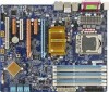
Secure Gigital / Memory Stick Serial ATA SPDIF AUX_IN CD_IN Connector Introduction 1) ATX1 (Auxuliary Power Connector) AC power cord should only be connected to your power supply unit after ATX power cable and other related devices are firmly connected to the mainboard. PIN No. 1 Definition +3.3V 2 +3.3V 3 GND 4 +5V 5 GND 6 +5V 7 GND 8 POK ATX 9 5VSB 10 +12V 11 +12V 12 +3.3V 13 +3.3V 14 -12V 15 GND 1 13 12 24 16 PSON 17 GND 18 GND 19 GND 20 -5V 21 +5V 22 +5V 23 +5V 24 GND 2 ) ATX2 (Auxuliary +12V Power Connector) ATX_12V 42 31 FDD Pin No. Definition 1 GND 2 GND 3 +12V 4 +12V CPU_FAN SYS_FAN PWR_FAN NB_FAN This connector (ATX +12V) is used only for CPU Core Voltage. 13
-
 1
1 -
2
-
3
-
4
-
5
-
6
-
7
-
 8
8 -
 9
9 -
 10
10 -
 11
11 -
 12
12 -
 13
13 -
 14
14 -
 15
15 -
 16
16 -
 17
17 -
 18
18 -
19
-
20
-
21
-
22
-
23
-
24
-
25
-
26
-
27
-
28
-
29
-
30
-
31
-
32
-
33
-
34
-
35
-
36
-
37
-
38
-
39
-
40
-
41
-
42
-
43
-
44
-
45
-
46
-
47
-
48
-
49
-
50
-
51
-
52
-
53
-
54
-
55
-
56
-
57
-
58
-
59
 |
 |

13
Connector Introduction
1) ATX1 (Auxuliary Power Connector)
AC power cord should only be connected to your power supply unit after ATX power cable
and other related devices are firmly connected
to the mainboard.
PIN No.
Definition
1
+3.3V
2
+3.3V
3
GND
4
+5V
5
GND
6
+5V
7
GND
8
POK
9
5VSB
10
+12V
11
+12V
12
+3.3V
13
+3.3V
14
-12V
15
GND
16
PSON
17
GND
18
GND
19
GND
20
-5V
21
+5V
22
+5V
23
+5V
24
GND
2 ) ATX2 (Auxuliary +12V Power Connector)
This connector (ATX +12V) is used only for
CPU Core Voltage.
Pin No.
Definition
1
GND
2
GND
3
+12V
4
+12V
24
13
12
1
4
1
2
3