Gigabyte GA-78LMT-S2PV Manual - Page 13
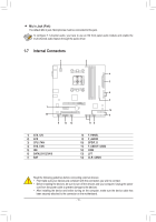
IDE IDE Connector, SATA2 0/1/2/3/4/5 SATA 3Gb/s Connectors, BAT Battery
 |
View all Gigabyte GA-78LMT-S2PV manuals
Add to My Manuals
Save this manual to your list of manuals |
Page 13 highlights
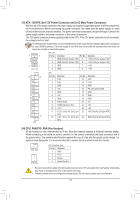
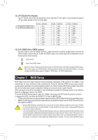
5) IDE (IDE Connector) The IDE connector supports up to two IDE devices such as hard drives and optical drives. Before attaching the IDE cable, locate the foolproof groove on the connector. If you wish to connect two IDE devices, remember to set the jumpers and the cabling according to the role of the IDE devices (for example, master or slave). (For information about configuring master/slave sDeEtBtUinGgs for the IDE devices, read the instructions from the device manufacturers.) PORT 1 2 DEBUG PORT 39 40 DEBUG DEBUG 6) SATA2 0/1/2/3/4/5 (SATA 3GPbOR/sT ConnePcOtRoTrs) The SATA connectors Each SATA connector conform supports atoDPsOESiBRnAUTgGTleAS3AGTbA/sDPdOEesBRtvaUTicnGed.aTrdheaAndMaDreSBco7m10pcaotinbtlerowlleitrhsSupApToArt1s.5RGAbID/s0s,tRanAdIDard1., RAID 10, and JBOD. Refer to Chapter 3, "Configuring SATA Hard Drive(s)," for instructions on configuring a RAID array. 1 SATA2 2 0 3 1 SATA2 5 4 7 Pin No. 1 2 3 4 5 6 7 Definition GND TXP TXN GND RXN RXP GND 1 7 1 7 •• A RAID 0 or RAID 1 configuration requires at least two hard drives. If more than two hard drives are to be used, the total number of hard drives must be an even number. •• A RAID 10 configuration requires four hard drives. 7) BAT (Battery) The battery provides power to keep the values (such as BIOS configurations, date, and time information) in the CMOS when the computer is turned off. Replace the battery when the battery voltage drops to a low level, or the CMOS values may not be accurate or may be lost. You may clear the CMOS values by removing the battery: 1. Turn off your computer and unplug the power cord. 2. Gently remove the battery from the battery holder and wait for one minute. (Or use a metal object like a screwdriver to touch the positive and negative terminals of the battery holder, making them short for 5 seconds.) 3. Replace the battery. 4. Plug in the power cord and restart your computer. •• Always turn off your computer and unplug the power cord before replacing the battery. •• Replace the battery with an equivalent one. Danger of explosion if the battery is replaced with an incorrect model. •• Contact the place of purchase or local dealer if you are not able to replace the battery by yourself or uncertain about the battery model. •• When installing the battery, note the orientation of the positive side (+) and the negative side (-) of the battery (the positive side should face up). •• Used batteries must be handled in accordance with local environmental regulations. - 13 -
-
 1
1 -
2
-
3
-
4
-
5
-
6
-
7
-
 8
8 -
 9
9 -
 10
10 -
 11
11 -
 12
12 -
 13
13 -
 14
14 -
 15
15 -
 16
16 -
 17
17 -
 18
18 -
19
-
20
-
21
-
22
-
23
-
24
-
25
-
26
-
27
-
28
-
29
-
30
-
31
-
32
-
33
-
34
-
35
-
36
 |
 |
