Gigabyte GA-790XTA-UD4 Manual
Gigabyte GA-790XTA-UD4 Manual
 |
UPC - 818313009364
View all Gigabyte GA-790XTA-UD4 manuals
Add to My Manuals
Save this manual to your list of manuals |
Gigabyte GA-790XTA-UD4 manual content summary:
- Gigabyte GA-790XTA-UD4 | Manual - Page 1
GA-790XTA-UD4 AM3 socket motherboard for AMD Phenom™ II processor/AMD Athlon™ II processor User's Manual Rev. 1001 12ME-790XTA4-1001R - Gigabyte GA-790XTA-UD4 | Manual - Page 2
Motherboard GA-790XTA-UD4 Nov. 20, 2009 Motherboard GA-790XTA-UD4 Nov. 20, 2009 - Gigabyte GA-790XTA-UD4 | Manual - Page 3
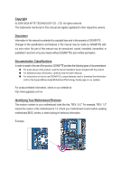
the product. For detailed product information, carefully read the User's Manual. For instructions on how to use GIGABYTE's unique features, read or download the information on/from the Support&Downloads\Motherboard\Technology Guide page on our website. For product-related information, check on our - Gigabyte GA-790XTA-UD4 | Manual - Page 4
Items...6 GA-790XTA-UD4 Motherboard Layout 7 Block Diagram...8 Chapter 1 Hardware Installation 9 1-1 Installation Precautions 9 1-2 Product Specifications 10 1-3 Installing the CPU and CPU Cooler 13 1-3-1 Installing the CPU 13 1-3-2 Installing the CPU Cooler 15 1-4 Installing the Memory 16 - Gigabyte GA-790XTA-UD4 | Manual - Page 5
Chipset Drivers 59 3-2 Application Software 60 3-3 Technical Manuals 60 3-4 Contact...61 3-5 System...61 3-6 Download Center 62 Chapter 4 Unique Features 63 4-1 Xpress Recovery2 63 4-2 BIOS Update Utilities 66 4-2-1 Updating the BIOS with the Q-Flash Utility 66 4-2-2 Updating the BIOS - Gigabyte GA-790XTA-UD4 | Manual - Page 6
Box Contents GA-790XTA-UD4 motherboard Motherboard driver disk User's Manual Quick Installation Guide One IDE cable Four SATA 3Gb/s cables I/O Shield • The box contents above are for reference only and the actual items shall depend on the product package you obtain. The box - Gigabyte GA-790XTA-UD4 | Manual - Page 7
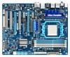
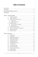
-UD4 Motherboard Layout KB_MS CPU_FAN RCA_SPDIF ATX_12V USB_1394_ESATA2 USB_1394_ESATA1 Socket AM3 PWR_FAN ATX R_USB USB30_LAN AUDIO NEC JMB362 F_AUDIO PCIEX1_1 AMD 790X IDE RTL8111D PCIEX16 IT8720 DDR3_1 DDR3_2 DDR3_3 DDR3_4 CD_IN CODEC PCIEX1_2 BAT PCI1 CLR_CMOS GA-790XTA-UD4 - Gigabyte GA-790XTA-UD4 | Manual - Page 8
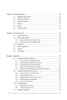
MHz) AM3 CPU CPU CLK+/- (200 MHz) DDR3 1866 (O.C.) (Note 2)/ 1333/1066 MHz Dual Channel Memory Hyper Transport 3.0 Switch PCI Express Bus x16 x1 x1 x1 PCIe CLK (100 MHz) 2 PCI Express x1 RTL8111D RJ45 LAN 6 SATA 3Gb/s ATA-133/100/66/33 IDE Channel PCI Bus TSB43AB23 3 IEEE 1394a AMD 790X - Gigabyte GA-790XTA-UD4 | Manual - Page 9
manual and follow these procedures: • Prior to installation, do not remove or break motherboard S/N wrist strap when handling electronic com- ponents such as a motherboard, CPU or memory. If you do not have an ESD wrist strap, steps or have a problem related to the use of the product, please consult - Gigabyte GA-790XTA-UD4 | Manual - Page 10
CPU Support for AM3 processors: AMD Phenom™ II processor/ AMD Athlon™ II processor/ (Go to GIGABYTE's website for the latest CPU support list.) Hyper Transport Bus 5200 MT/s Chipset Memory Audio North Bridge: AMD 790X South Bridge: AMD SB750 4 x 1.5V DDR3 DIMM sockets supporting - Gigabyte GA-790XTA-UD4 | Manual - Page 11
USB w Chipset: - Up to 10 USB 2.0/1.1 ports (6 on the back pin ATX main power connector Connectors w 1 x 8-pin ATX 12V power connector w 1 x floppy disk drive connector w 1 x IDE connector w 6 x SATA 3Gb/s connectors w 2 x SATA 6Gb/s connectors w 1 x CPU - Gigabyte GA-790XTA-UD4 | Manual - Page 12
Security (OEM version) Operating System w Support for Microsoft® Windows® 7/Vista/XP Form Factor w ATX Form Factor; 30.5cm x 24.4cm (Note 1) Due to Windows 32-bit operating system limitation, when more than 4 GB of physical memory is installed, the actual memory size displayed will be less than - Gigabyte GA-790XTA-UD4 | Manual - Page 13
sure that the motherboard supports the CPU. (Go to GIGABYTE's website for the latest CPU support list.) • Always turn off the computer and unplug the power cord from the power outlet before installing the CPU to prevent hardware damage. • Locate the pin one of the CPU. The CPU cannot be inserted - Gigabyte GA-790XTA-UD4 | Manual - Page 14
below to correctly install the CPU into the motherboard CPU socket. • Before installing the CPU, make sure to turn off the computer and unplug the power cord from the power outlet to prevent damage to the CPU. • Do not force the CPU into the CPU socket. The CPU cannot fit in if oriented incorrectly - Gigabyte GA-790XTA-UD4 | Manual - Page 15
lock into place. (Refer to your CPU cooler installation manual for instructions on installing the cooler.) Step 5: Finally, attach the power connector of the CPU cooler to the CPU fan header (CPU_FAN) on the motherboard. Use extreme care when removing the CPU cooler because the thermal grease/tape - Gigabyte GA-790XTA-UD4 | Manual - Page 16
. If you are unable to insert the memory, switch the direction. 1-4-1 Dual Channel Memory Configuration This motherboard provides four DDR3 memory sockets and supports Dual Channel Technology. After the memory is installed, the BIOS will automatically detect the specifications and capacity of - Gigabyte GA-790XTA-UD4 | Manual - Page 17
to install DDR3 DIMMs on this motherboard. Notch DDR3 DIMM A DDR3 memory module has a notch, so it can only fit in one direction. Follow the steps below to correctly install your memory modules in the memory sockets. Step 1: Note the orientation of the memory module. Spread the retaining clips at - Gigabyte GA-790XTA-UD4 | Manual - Page 18
an expansion card: • Make sure the motherboard supports the expansion card. Carefully read the manual that came with your expansion card. • Always If necessary, go to BIOS Setup to make any required BIOS changes for your expansion card(s). 7. Install the driver provided with the expansion card - Gigabyte GA-790XTA-UD4 | Manual - Page 19
System Requirements - Windows 7, Windows Vista, or Windows XP operating system - A CrossFireX-supported motherboard with two PCI Express x16 slots and correct driver - Two CrossFireX-ready graphics cards of identical brand and chip and correct driver - Two CrossFire bridge connectors (Note - Gigabyte GA-790XTA-UD4 | Manual - Page 20
IEEE 1394 port supports the IEEE 1394a SATA 3Gb/s standard and is compatible with SATA 1.5Gb/s standard. Use the port to connect an external SATA device. Refer to Chapter 5, "Configuring SATA Hard Drive(s)," for instructions on configuring a RAID 10 remove it from the motherboard. • When removing the - Gigabyte GA-790XTA-UD4 | Manual - Page 21
to perform different functions via the audio software. Only microphones still MUST be connected to the default Mic in jack ( ). Refer to the instructions on setting up a 2/4/5.1/7.1-channel audio configuration in Chapter 5, "Configuring 2/4/5.1/7.1-Channel Audio." - 21 - Hardware Installation - Gigabyte GA-790XTA-UD4 | Manual - Page 22
1-8 Internal Connectors 13 5 2 7 12 10 13 8 19 14 15 9 18 1) ATX_12V_2X4 2) ATX 3) CPU_FAN 4) SYS_FAN1/SYS_FAN2 5) PWR_FAN 6) FDD 7) IDE 8) SATA2_0/1/2/3/4/5 9) GSATA3_6/7 10) BAT 6 17 16 4 11 4 been securely attached to the connector on the motherboard. Hardware Installation - 22 - - Gigabyte GA-790XTA-UD4 | Manual - Page 23
. Definition 1 GND (Only for 2x4-pin 12V) 2 GND (Only for 2x4-pin 12V) 3 GND 4 GND 5 +12V (Only for 2x4-pin 12V) 6 +12V (Only for 2x4-pin 12V) 7 +12V 8 +12V 12 24 1 13 ATX ATX: Pin No. 1 2 3 4 5 6 7 8 9 10 11 12 Definition Pin No. 3.3V 13 3.3V 14 GND 15 +5V 16 GND 17 +5V 18 GND - Gigabyte GA-790XTA-UD4 | Manual - Page 24
) system fan headers, and a 3-pin power fan header (PWR_FAN). Most fan headers possess a foolproof insertion design. When connecting a fan cable, be sure to connect it in the correct orientation (the black connector wire is the ground wire). The motherboard supports CPU fan speed control, which - Gigabyte GA-790XTA-UD4 | Manual - Page 25
with SATA 1.5Gb/s standard. Each SATA connector supports a single SATA device. The AMD SB750 controller supports RAID 0, RAID 1, RAID 5, RAID 10, and JBOD. Refer to Chapter 5, "Configuring SATA Hard Drive(s)," for instructions on configuring a RAID array. G.QBOFM G.QBOFM G.QBOFM Pin No - Gigabyte GA-790XTA-UD4 | Manual - Page 26
SATA connector supports a single SATA device. The Marvell 9128 controller supports RAID 0 and RAID 1. Refer to Chapter 2, "BIOS Setup," "Integrated Peripherals," and Chapter 5, "Configuring SATA Hard Drive(s)," for instructions on configuring a RGA.IQDBOaFrrMay. GSATA3_7 7 1 7 1 GSATA3_6 Pin - Gigabyte GA-790XTA-UD4 | Manual - Page 27
status by issuing a beep code. One single short beep will be heard if no problem is detected at system startup. If a problem is detected, the BIOS may issue beeps in different patterns to indicate the problem. Refer to Chapter 5, "Troubleshooting," for information about beep codes. • HD (Hard Drive - Gigabyte GA-790XTA-UD4 | Manual - Page 28
5 Line Out (R) 6 GND 6 NC 7 FAUDIO_JD 7 NC 8 No Pin 8 No Pin 9 LINE2_L 9 Line Out (L) 10 GND 10 NC • The front panel audio header supports HD audio by default. If your chassis provides an AC'97 front panel audio module, refer to the instructions on how to activate AC'97 functionality via - Gigabyte GA-790XTA-UD4 | Manual - Page 29
contact the local dealer. 1 Pin No. Definition 1 Power 2 SPDIFI 3 GND 15) SPDIF_OUT (S/PDIF Out Header) This header supports digital S/PDIF Out and connects a S/PDIF digital audio cable (provided by expansion cards) for digital audio output from your motherboard to certain expansion cards like - Gigabyte GA-790XTA-UD4 | Manual - Page 30
IEEE 1394a bracket. For purchasing the optional IEEE 1394a bracket, please contact the local dealer. Pin No. Definition 9 1 1 TPA+ 10 2 2 TPA- 3 GND 4 GND 5 TPB+ 6 TPB- 7 Power (12V) 8 Power (12V) 9 No Pin 10 GND • Do not plug the USB bracket cable into the IEEE 1394a header. • Prior - Gigabyte GA-790XTA-UD4 | Manual - Page 31
the jumper. Failure to do so may cause damage to the motherboard. • After system restart, go to BIOS Setup to load factory defaults (select Load Optimized Defaults) or manually configure the BIOS settings (refer to Chapter 2, "BIOS Setup," for BIOS configurations). - 31 - Hardware Installation - Gigabyte GA-790XTA-UD4 | Manual - Page 32
Hardware Installation - 32 - - Gigabyte GA-790XTA-UD4 | Manual - Page 33
problems using the current version of BIOS, it is recommended that you not flash the BIOS. To flash the BIOS, do it with caution. Inadequate BIOS flashing may result in system malfunction. • BIOS will emit a beep code during the POST. Refer to Chapter 5, "Troubleshooting," for the beep codes - Gigabyte GA-790XTA-UD4 | Manual - Page 34
Ally Copyright (C) 1984-2009, Award Software, Inc. Motherboard Model BIOS Version GA-790XTA-UD4 D4 . . . . : BIOS Setup : XpressRecovery2 : Boot Menu : Qflash 10/28/2009-RD780-SB750-7A66AG00C-00 Function Keys Function Keys SATA Mode Message: "SATA is found running at IDE MODE - Gigabyte GA-790XTA-UD4 | Manual - Page 35
Save & Exit Setup Change CPU's Clock & Voltage F11: Save CMOS to BIOS F12: Load CMOS from BIOS BIOS Setup Program Function Keys F2> Move cursor to the Item Help block on the right (submenus only) Restore the previous BIOS settings for the current submenus Load the Fail-Safe BIOS - Gigabyte GA-790XTA-UD4 | Manual - Page 36
the clock, frequency and voltages of your CPU, memory, etc. Standard CMOS Features Use this menu to configure the system time and date, hard drive types, floppy disk drive types, and the type of errors that stop the system boot, etc. Advanced BIOS Features Use this menu to configure the device - Gigabyte GA-790XTA-UD4 | Manual - Page 37
you made is dependent on your overall system configurations. Incorrectly doing overclock/overvoltage may result in damage to CPU, chipset, or memory and reduce the useful life of these components. This page is Voltage Control item to Auto to optimize the system voltage settings. - 37 - BIOS Setup - Gigabyte GA-790XTA-UD4 | Manual - Page 38
number of cores available depends on the CPU being used). Manual Allows you to individually enable/disable CPU Core 2 and Core 3. CPU core 2 (Note) Enables or disables CPU Core 2. (Default: Enabled) (Note) This item is present only if you install a CPU that supports this feature. BIOS Setup - Gigabyte GA-790XTA-UD4 | Manual - Page 39
8 bit. 16 bit Sets HT Link Width to 16 bit. HT Link Frequency Allows you to manually set the frequency for the HT Link between the CPU and chipset. Auto BIOS will automatically adjust the HT Link Frequency. (Default) x1~x10 Sets HT Link Frequency to x1~x10 (200 MHz~2.0 GHz). VGA Core Clock - Gigabyte GA-790XTA-UD4 | Manual - Page 40
Allows you to set memory control mode. Ganged Sets memory control mode to single dual-channel. Unganged Sets memory control mode to two single-channel. (Default) DDR3 Timing Items Manual allows all DDR3 Timing items below to be configurable. Options are: Auto (default), Manual. BIOS Setup - 40 - Gigabyte GA-790XTA-UD4 | Manual - Page 41
/Cmd drive strength Options are: Auto (default), 1.0x, 1.25x, 1.5x, 2.0x. CHA CS/ODT drive strength Options are: Auto (default), 1.0x, 1.25x, 1.5x, 2.0x. - 41 - BIOS Setup - Gigabyte GA-790XTA-UD4 | Manual - Page 42
simultaneously access different channels of the memory to increase memory performance and stability. (Default: Enabled) ******** System Voltage Optimized ******** System Voltage Control Determines whether to manually set the system voltages. Auto lets the BIOS automatically set the system voltages - Gigabyte GA-790XTA-UD4 | Manual - Page 43
the CPU voltage as required. The adjustable range is dependent on the CPU being installed. (Default: Normal) Note: Increasing CPU voltage may result in damage to your CPU or reduce the useful life of the CPU. Normal CPU Vcore Displays the normal operating voltage of your CPU. - 43 - BIOS Setup - Gigabyte GA-790XTA-UD4 | Manual - Page 44
] [None] [None] [None] Drive A Floppy 3 Mode Support [1.44M, 3.5"] [Disabled] Halt On [All, But Keyboard] Software Standard CMOS Features Base Memory Extended Memory 640K 2046M Item Help Menu SATA device on this channel. IDE Channel 0, 1 Master/Slave Configure your IDE - Gigabyte GA-790XTA-UD4 | Manual - Page 45
wish to enter the parameters manually, refer to the information on ", 720K/3.5", 1.44M/3.5", 2.88M/3.5". Floppy 3 Mode Support Allows you to specify whether the installed floppy disk Memory These fields are read-only and are determined by the BIOS POST. Base Memory Also called conventional memory - Gigabyte GA-790XTA-UD4 | Manual - Page 46
AMD C1E Support Enables or disables the C1E CPU power-saving function in system halt state. When enabled, the CPU core AMD K8 Cool&Quiet control Auto Lets the AMD Cool'n'Quiet driver dynamically adjust the CPU when you enter BIOS Setup. After configuring this item, set the password(s) under - Gigabyte GA-790XTA-UD4 | Manual - Page 47
Away Mode Enables or disables Away Mode in Windows XP Media Center operating system. Away Mode allows GIGABYTE Logo at system startup. Disabled displays normal POST message. (Default: Enabled) Backup BIOS Image to HDD Allows the system to copy the BIOS image file to the hard drive. If the system BIOS - Gigabyte GA-790XTA-UD4 | Manual - Page 48
of the integrated SATA2_0~SATA2_3 controller. Native IDE Allows the SATA controller to operate in Native IDE mode. (Default) Enable Native IDE mode if you wish to install operating systems that support Native mode. RAID Enables RAID for the SATA controller. BIOS Setup - 48 - - Gigabyte GA-790XTA-UD4 | Manual - Page 49
that allows the storage driver to enable advanced Serial ATA features such as Native Command Queuing and hot plug. OnChip SATA Port4/5 Type (AMD SB750, SATA2_4~SATA2_5 connectors) This option is configurable only when OnChip SATA Type is set to RAID or AHCI. Configures the operating mode - Gigabyte GA-790XTA-UD4 | Manual - Page 50
motherboard attached to the motherboard, the Status problem is detected on the LAN cable connected to a Gigabit hub or a 10 10/100/1000 Mbps in Windows mode or when the LAN Boot ROM is activated. When a Cable Problem Occurs... If a cable problem are not used in a 10/100 Mbps environment, so their - Gigabyte GA-790XTA-UD4 | Manual - Page 51
disables the integrated USB 2.0 controller. (Default: Enabled) USB Keyboard Support Allows USB keyboard to be used in MS-DOS. (Default: Enabled) USB Mouse Support Allows USB mouse to be used in MS-DOS. (Default: are: Auto, 2F8/IRQ3, 3F8/IRQ4(default), 3E8/IRQ4, 2E8/IRQ3, Disabled. - 51 - BIOS Setup - Gigabyte GA-790XTA-UD4 | Manual - Page 52
any time. S3(STR) Enables the system to enter the ACPI S3 (Suspend to RAM) sleep state (default). In S3 sleep state, the system appears to be off from a modem that supports wake-up function. (Default: Disabled) (Note) Supported on Windows Vista operating system only. BIOS Setup - 52 - - Gigabyte GA-790XTA-UD4 | Manual - Page 53
ATX power supply providing at least 1A on the +5VSB lead. (Default: Enabled) HPET Support (Note) Enables or disables High Precision Event Timer (HPET) for Windows the return of the AC power. Memory The system returns to its last Supported on Windows Vista operating system only. - 53 - BIOS Setup - Gigabyte GA-790XTA-UD4 | Manual - Page 54
12V Current System Temperature Current CPU Temperature Current CPU Software PC Health Status CPU Smart FAN Mode CPU overheating protection function. When enabled, the CPU core voltage and ratio will be reduced when the CPU detection device attached to the motherboard CI header. If the - Gigabyte GA-790XTA-UD4 | Manual - Page 55
FAN Control is set to Enabled. Auto Lets the BIOS automatically detect the type of CPU fan installed and sets the optimal CPU fan control mode. (Default) Voltage Sets Voltage mode for a 3-pin CPU fan. PWM Sets PWM mode for a 4-pin CPU fan. System Smart FAN Control Enables or disables the - Gigabyte GA-790XTA-UD4 | Manual - Page 56
BIOS settings for the motherboard. 2-10 BIOS F12: Load CMOS from BIOS Press on this item and then press the key to load the optimal BIOS default settings. The BIOS defaults settings help the system to operate in optimum state. Always load the Optimized defaults after updating the BIOS - Gigabyte GA-790XTA-UD4 | Manual - Page 57
Exit Setup Exit Without Saving ESC: Quit F8: Q-Flash Select Item F10: Save & Exit Setup Change/Set/Disable Password F11: Save CMOS to BIOS F12: Load CMOS from BIOS Press on this item and type the password with up to 8 characters and then press . You will be requested to confirm - Gigabyte GA-790XTA-UD4 | Manual - Page 58
Press on this item and press the key. This saves the changes to the CMOS and exits the BIOS Setup program. Press or to return to the BIOS Setup Main Menu. 2-13 Exit Without Saving CMOS Setup Utility-Copyright (C) 1984-2009 Award Software MB Intelligent Tweaker(M.I.T.) Load - Gigabyte GA-790XTA-UD4 | Manual - Page 59
are installed, follow the on-screen instructions to restart your system. You can install other applications included in the motherboard driver disk. • For USB 2.0 driver support under the Windows XP operating system, please install the Windows XP Service Pack 1 or later. After installing the SP1 - Gigabyte GA-790XTA-UD4 | Manual - Page 60
applications that GIGABYTE develops and some free software. You can click the Install button on the right of an item to install it. 3-3 Technical Manuals This page provides GIGABYTE's application guides, content descriptions for this driver disk, and the motherboard manuals. Drivers Installation - Gigabyte GA-790XTA-UD4 | Manual - Page 61
3-4 Contact For the detailed contact information of the GIGABYTE Taiwan headquarter or worldwide branch offices, click the URL on this page to link to the GIGABYTE website. 3-5 System This page provides the basic system information. - 61 - Drivers Installation - Gigabyte GA-790XTA-UD4 | Manual - Page 62
3-6 Download Center To update the BIOS, drivers, or applications, click the Download Center button to link to the GIGABYTE website. The latest version of the BIOS, drivers, or applications will be displayed. Drivers Installation - 62 - - Gigabyte GA-790XTA-UD4 | Manual - Page 63
advanced (10 GB or and drivers are installed. memory • VESA compatible graphics card • Windows XP with SP1 or later, Windows supported. • Hard drives in RAID/AHCI mode are not supported. Installation and Configuration: Turn on your system to boot from the Windows Vista setup disk. A. Installing Windows - Gigabyte GA-790XTA-UD4 | Manual - Page 64
hard drive, make sure to leave unallocated space (10 GB or more is recommended; actual size requirements save the backup file. B. Accessing Xpress Recovery2 1. Boot from the motherboard driver disk to access Xpress Recovery2 for the first time. When you see disk allocation. Unique Features - 64 - - Gigabyte GA-790XTA-UD4 | Manual - Page 65
D. Using the Restore Function in Xpress Recovery2 Select RESTORE to restore the backup to your hard drive in case the system breaks down. The RESTORE option will not be present if no backup is created before. E. Removing the Backup Step 1: If you wish to remove the backup file, select REMOVE. Step - Gigabyte GA-790XTA-UD4 | Manual - Page 66
, if the BIOS update file is saved to a hard drive in RAID/AHCI mode or a hard drive attached to an independent IDE/SATA controller, use the key during the POST to access Q-Flash. Award Modular BIOS v6.00PG, An Energy Star Ally Copyright (C) 1984-2009, Award Software, Inc. GA-790XTA-UD4 D5 - Gigabyte GA-790XTA-UD4 | Manual - Page 67
system. • If the BIOS update file is saved to a hard drive in RAID/AHCI mode or a hard drive attached to an independent IDE/SATA controller, use the < BIOS update file and press . Make sure the BIOS update file matches your motherboard model. Step 2: The process of the system reading the BIOS - Gigabyte GA-790XTA-UD4 | Manual - Page 68
. Step 5: During the POST, press to enter BIOS Setup. Select Load Optimized Defaults and press to load BIOS defaults. System will re-detect all peripheral devices after a BIOS update, so we recommend that you reload BIOS defaults. CMOS Setup Utility-Copyright (C) 1984-2009 Award - Gigabyte GA-790XTA-UD4 | Manual - Page 69
. If the BIOS update file for your motherboard is not present on the @BIOS server site, please manually download the BIOS update file from GIGABYTE's website and follow the instructions in "Update the BIOS without Using the Internet Update Function" below. 2. Update the BIOS without Using the - Gigabyte GA-790XTA-UD4 | Manual - Page 70
in EasyTune 6 may differ by motherboard model. Grayed-out area(s) indicates that the item is not configurable or the function is not supported. Incorrectly doing overclock/overvoltage may result in damage to the hardware components such as CPU, chipset, and memory and reduce the useful life of - Gigabyte GA-790XTA-UD4 | Manual - Page 71
The Easy Energy Saver Interface A. Meter Mode In Meter Mode, GIGABYTE Easy Energy Saver shows how much power they have saved in a Utility Update (Check for the latest utility version) • The above data is for reference only. Actual performance may vary depending on motherboard model. • CPU Power - Gigabyte GA-790XTA-UD4 | Manual - Page 72
10 Total Mode Switch 11 Close (Application will enter Stealth Mode) 12 Minimize (Application will continue to run in taskbar) 13 INFO/Help 14 Live Utility Update . (Note 1) Maximize system power saving with Dynamic CPU Frequency Function; system performance may be affected. (Note - Gigabyte GA-790XTA-UD4 | Manual - Page 73
for using Q-Share After installing Q-Share from the motherboard driver disk, go to Start>All Programs>GIGABYTE>Q-Share. exe to launch the Q-Share tool. shared data folder Changes the data folder to be shared (Note) Updates Q-Share online Displays the current Q-Share version Exits Q-Share ( - Gigabyte GA-790XTA-UD4 | Manual - Page 74
Services technology, Time Repair allows you to quickly back up and restore your system data in the Windows Vista operating system. Time Repair supports NTFS file system and can restore system data on PATA and SATA . • Each storage volume can accommodate 64 shadow copies. When this limit is reached - Gigabyte GA-790XTA-UD4 | Manual - Page 75
hard drive(s) in your computer. B. Configure SATA controller mode in BIOS Setup. C. Configure a RAID array in RAID BIOS. (Note 1) D. Make a floppy disk containing the SATA RAID/AHCI driver for Windows XP. (Note 2) E. Install the SATA RAID/AHCI driver (Note 2) and operating system. Before you begin - Gigabyte GA-790XTA-UD4 | Manual - Page 76
BIOS Setup during the POST (Power-On Self-Test). Ensure OnChip SATA Controller is enabled under Integrated Peripherals. To enable RAID for the SATA2_0/1/2/3 connectors, set OnChip SATA Type to RAID. To enable RAID for the SATA2_4/5 connectors, set OnChip SATA Type to RAID and set OnChip SATA - Gigabyte GA-790XTA-UD4 | Manual - Page 77
C. Configuring RAID set in RAID BIOS Enter the RAID BIOS setup utility to configure a RAID array. Skip this step and proceed with the installation of Windows operating system for a non-RAID configuration. Step 1: After the POST memory test begins and before the operating system boot begins, look for - Gigabyte GA-790XTA-UD4 | Manual - Page 78
Mode [ Define LD Menu ] Total Drv LD 1 RAID 0 0 Stripe Block: 64 KB Gigabyte Boundary: ON [ Drives Assignments ] Channel:ID Drive Model 1:Mas WDC WD800JD-22LSA0 2:Mas WDC WD800JD-22LSA0 Capabilities SATA 3G SATA 3G Fast Init: ON Cache Mode: WriteThru Capacity (GB) 79 - Gigabyte GA-790XTA-UD4 | Manual - Page 79
window below will appear. Press Ctrl-Y to Modify Array Capacity or press any other key to use maximum capacity... Figure 7 7. Press + to set the capacity of the RAID Model Capabilities WDC WD800JD-22LSA0 SATA 3G Extent 1 WDC WD800JD-22LSA0 SATA 3G Extent 1 Capacity (GB - Gigabyte GA-790XTA-UD4 | Manual - Page 80
Menu ] Total Drv Capacity (GB) Status LD 1 RAID 0 2 157.99 Functional Stripe Block: 64KB Cache Mode: WriteThru [ Drives Assignments ] Channel:ID 1:Mas 2:Mas Drive Model WDC WD800JD-22LSA0 WDC WD800JD-22LSA0 Capabilities SATA 3G SATA 3G Press Ctrl-Y to delete the data - Gigabyte GA-790XTA-UD4 | Manual - Page 81
SATA port on the motherboard. The JMicron JMB362 SATA controller controls the eSATA ports on the back panel. Then connect the power connector from your power supply to the hard drive. B. Configuring SATA controller mode in BIOS ] [Enabled] [RAID] [As SATA Type] [Enabled] [Enabled] [RAID] [Enabled] [ - Gigabyte GA-790XTA-UD4 | Manual - Page 82
C. Configuring a RAID array in RAID BIOS Enter the RAID BIOS setup utility to configure a RAID array. Skip this step and proceed to the installation of Windows operating system for a non-RAID configuration. After the POST memory test begins and before the operating system boot begins, look for a - Gigabyte GA-790XTA-UD4 | Manual - Page 83
Array: In the main screen, press on the Create RAID Disk Drive item. Then the Create New RAID screen appears (Figure 4). GIGABYTE Technology Corp. PCIE-to-SATAII/IDE RAID Controller BIOSv1.06.59 [ Create New RAID ] Name: Level: Disks: Block: Size: GRAID_ 0-Stripe Select Disk 128 KB - Gigabyte GA-790XTA-UD4 | Manual - Page 84
a RAID mode is selected, RAID BIOS automatically assigns the two hard drives installed as the RAID drives. 4. Set Block Size (RAID 0 only): Under the Block item, use the up or down arrow key to select the stripe block size (Figure 6), ranging from 4 KB to 128 KB. Press . GIGABYTE Technology - Gigabyte GA-790XTA-UD4 | Manual - Page 85
block. Select the array and press . A small window displaying the array information will appear in the center of the screen (Figure 9). GIGABYTE Technology Corp. PCIE-to-SATAII/IDE RAID Controller BIOSv1.06.59 [ Main Menu ] Create RAID Disk Drive Delete RAID Disk Drive Revert HDD to Non - Gigabyte GA-790XTA-UD4 | Manual - Page 86
GB Normal Members(HDDx) 01 [fgTAB]-Switch Window [hi]-Select ITEM Figure 10 [ENTER]-Action [ESC]-Exit Now, you may proceed to create the SATA RAID/AHCI driver diskette and the installation of the SATA RAID/ AHCI driver and operating system. Delete the RAID Array: To delete the array, select - Gigabyte GA-790XTA-UD4 | Manual - Page 87
, depending on your requirements (Figure 1). (In AHCI mode, installation of the SATA AHCI driver is required during Windows XP installation. Refer to section, "5-1-4" for more information.) Step 2: To create a RAID array, press on the GSATA RAID Configuration item (Figure 1) to enter the - Gigabyte GA-790XTA-UD4 | Manual - Page 88
22L PD 8: WDC WD800JD-22L Information Vendor ID : Device ID : Revision ID : BIOS Version : Firmware Version : PCIe Speed rate : Configure SATA as : 1B4B 91A3 B1 1.0.0.1006 2.1.0.1314 2.56Gbps IDE Mode Help Marvell RAID on chip controller. ENTER: Operation F10: Exit/Save ESC: Return Figure - Gigabyte GA-790XTA-UD4 | Manual - Page 89
sequence and press after each step. Steps: 1. RAID Level: Select a RAID level. Options include RAID 0 (Stripe) and RAID 1 (Mirror). 2. Stripe Size: Select the stripe block size. Options include 32 KB and 64 KB. 3. Gigabyte Rounding: Select whether to permit the installation of a replacement - Gigabyte GA-790XTA-UD4 | Manual - Page 90
-22L Free Physical Disks Information Vendor ID : Device ID : Revision ID : BIOS Version : Firmware Version : PCIe Speed rate : Configure SATA as : 1B4B 91A3 B1 1.0.0.1006 2.1.0.1314 2.56Gbps IDE Mode Help Marvell RAID on chip controller. ENTER: Operation F10: Exit/Save ESC: Return Figure - Gigabyte GA-790XTA-UD4 | Manual - Page 91
SATA driver diskette (for AHCI mode) and the installation of the SATA driver and operating system. Delete the RAID ID : BIOS Version : Firmware Version : PCIe Speed rate : Configure SATA as motherboard driver disk, then go to Application Software\Install GIGABYTE Utilities and select Marvell Raid - Gigabyte GA-790XTA-UD4 | Manual - Page 92
(AHCI mode) Bootdrv\SB7xxW7\AHCI\x86 Windows 7 32-bit (RAID mode) Bootdrv\SB7xxW7\RAID\x86 Windows 7 64-bit (AHCI mode) Bootdrv\SB7xxW7\AHCI\x64 Windows 7 64-bit (RAID mode) Bootdrv\SB7xxW7\RAID\x64 (Note 2) Change the directory from \32bit to \64bit for copying the Windows 64-bit driver - Gigabyte GA-790XTA-UD4 | Manual - Page 93
. For example, from the menu in Figure 5, • For the AMD SB750, select 3) SB7xx AHCI/RAID Driver for XP for Windows XP operating system. • For the JMicron JMB362, select 1) GIGABYTE GSATA driver for 32bit system for Windows 32-bit op- erating system. • For the Marvell 9128, select 7) Marvell - Gigabyte GA-790XTA-UD4 | Manual - Page 94
containing the SATA RAID/AHCI driver and press . Then a controller menu similar to Figure 2 below will appear. Select AMD AHCI Compatible RAID Controller-x86 platform and press . Windows Setup You have chosen to configure a SCSI Adapter for use with Windows, using a device support disk - Gigabyte GA-790XTA-UD4 | Manual - Page 95
the SATA RAID/AHCI driver and press . Then a controller menu similar to Figure 3 below will appear. Select RAID/AHCI Driver for GIGABYTE GBB36X Controller (x32) and press . Windows Setup You have chosen to configure a SCSI Adapter for use with Windows, using a device support disk - Gigabyte GA-790XTA-UD4 | Manual - Page 96
flash drive that contains the SATA RAID/AHCI driver (Method B), then specify the location of the driver (Figure 6). Note: For users using a SATA optical drive, be sure to copy the driver files from the motherboard driver disk to a USB flash drive before installing Windows Vista (go to the BootDrv - Gigabyte GA-790XTA-UD4 | Manual - Page 97
Step 3: When a screen as shown in Figure 7 appears, select AMD AHCI Compatible RAID Controller and press Next. Figure 7 Step 4: After the driver is loaded, the RAID drive will appear. Select the RAID drive and then press Next to continue the OS installation (Figure 8). Figure 8 - 97 - Appendix - Gigabyte GA-790XTA-UD4 | Manual - Page 98
flash drive that contains the SATA RAID/ AHCI driver (Method B), then specify the location of the driver (Figure 10). Note: For users using a SATA optical drive, be sure to copy the driver files from the motherboard driver disk to a USB flash drive before installing Windows Vista (go to the BootDrv - Gigabyte GA-790XTA-UD4 | Manual - Page 99
Step 3: When a screen as shown in Figure 11 appears, select GIGABYTE GBB36X Controller and click Next. Figure 11 Step 4: After the driver is loaded, select the RAID/AHCI drive(s) where you want to install the operating system and then click Next to continue the OS installation (Figure 12). Figure - Gigabyte GA-790XTA-UD4 | Manual - Page 100
new drive is added to replace a failed drive to rebuild a RAID 1 array. For the AMD SB750: While in the operating system, make sure the chipset drivers and ATi RAID Utility have been installed from the motherboard driver disk. Then launch the AMD RAIDXpert from All Programs in the Start Menu. Step - Gigabyte GA-790XTA-UD4 | Manual - Page 101
the screen. When done, the status of the array will display as Normal. Gigabyte Technology Corp. RAID Setup Utility v1.07.06 [ Main Menu ] Create RAID Disk Drive Delete RAID Disk Drive Revert HDD to Non-RAID Solve Mirror Conflict Rebuild Mirror Drive Save And Exit Setup Exit Without Saving [ Hard - Gigabyte GA-790XTA-UD4 | Manual - Page 102
Rebuilding in the operating system Make sure the JMicron JMB362 SATA controller driver has been installed from the motherboard driver disk. Launch the GIGABYTE RAID CONFIGURER from All Programs in the Start menu. Step 1: In the GIGABYTE RAID CONFIGURER screen, right-click on the array to be rebuilt - Gigabyte GA-790XTA-UD4 | Manual - Page 103
perform the rebuild, you must enter the GSATA RAID Configuration menu in BIOS Setup. Step 1: After the system starts, enter the BIOS Setup program and go to Integrated Peripherals. Press on GSATA RAID Configuration to access the RAID configuration menu. Move the selection bar to the array - Gigabyte GA-790XTA-UD4 | Manual - Page 104
Rebuild Process To resume the stopped rebuild process, enter the GSATA RAID Configuration menu in BIOS Setup again. Move the selection bar to the array to be last rebuild progress will be rounded down to the nearest multiple of 10 percent (as shown in the BGA Rebuild item). For example, if you - Gigabyte GA-790XTA-UD4 | Manual - Page 105
2/4/5.1/7.1-Channel Audio The motherboard provides six audio jacks on the back panel which support 2/4/5.1/7.1-channel (Note) Configuring Speakers (The following instructions use Windows Vista as the example operating system.) Step 1: After installing the audio driver, the HD Audio Manager icon - Gigabyte GA-790XTA-UD4 | Manual - Page 106
Step 2: Connect an audio device to an audio jack. The The current connected device is dialog box appears. Select the device according to the type of device you connect. Then click OK. Step 3: On the Speakers screen, click the Speaker Configuration tab. In the Speaker Configuration list, select - Gigabyte GA-790XTA-UD4 | Manual - Page 107
S/PDIF In 1. Installing the S/PDIF In Cable: Step 1: First, attach the connector at the end of the cable to the SPDIF_IN header on your motherboard. Step 2: Secure the metal bracket to the chassis back panel with a screw. 2. Configuring S/PDIF In: On the Digital Input screen, click the Default - Gigabyte GA-790XTA-UD4 | Manual - Page 108
the Default Format tab and then select the sample rate and bit depth. Click OK to complete. (Note) If you have connected a S/PDIF digital audio cable (provided by expansion cards) to the 2-pin S/PDIF Out header (SPDIF_O) on the motherboard to output digital audio to your expansion card, you can - Gigabyte GA-790XTA-UD4 | Manual - Page 109
be transformed into multi-channel audio, creating a virtual surround sound environment . (Note) Install the Dolby GUI Software driver from the motherboard driver disk. Click the Start icon Programs, Dolby Control Center to access the utility. (The following illustration demonstrates a 7.1-speaker - Gigabyte GA-790XTA-UD4 | Manual - Page 110
5-2-4 Configuring Microphone Recording Step 1: After installing the audio driver, the HD Audio Manager icon will appear in the notification area. Double-click the icon to access the HD Audio Manager. Step 2: Connect your microphone - Gigabyte GA-790XTA-UD4 | Manual - Page 111
Step 4: To raise the recording and playback volume for the microphone, click the Microphone Boost icon on the right of the Recording Volume slider and set the Microphone Boost level. Step 5: After completing the settings above, click Start, point to All Programs, point to Accessories, and then click - Gigabyte GA-790XTA-UD4 | Manual - Page 112
. Be sure to save the recorded audio file upon completion. B. Playing the Recorded Sound You can play your recording in a digital media player program that supports your audio file format. Appendix - 112 - - Gigabyte GA-790XTA-UD4 | Manual - Page 113
download the audio driver from GIGABYTE's website to install. For more details, go to the Support&Downloads\Motherboards\FAQ page on our website and search for "onboard HD audio driver." Q: What do the beeps emitted during the POST mean? A: The following Award BIOS beep code descriptions may help - Gigabyte GA-790XTA-UD4 | Manual - Page 114
the motherboard. Yes The problem is verified and solved. Check if the memory is installed properly on the memory slot. No Correctly insert the memory into the memory socket. Yes The problem is verified and solved. Insert the graphics card. Connect the ATX main power cable and the 12V power - Gigabyte GA-790XTA-UD4 | Manual - Page 115
successfully). No The IDE/SATA device, connector, or cable might fail. The problem is verified and solved. END If the procedure above is unable to solve your problem, contact the place of purchase or local dealer for help. Or go to the Support&Downloads\Technical Service Zone page to submit - Gigabyte GA-790XTA-UD4 | Manual - Page 116
GIGABYTE. Our Commitment to Preserving the Environment In addition to high-efficiency performance, all GIGABYTE motherboards local government office, your household waste disposal service or where you purchased the product for user's manual and we will be glad to help you with your effort. Appendix - Gigabyte GA-790XTA-UD4 | Manual - Page 117
Finally, we suggest that you practice other environmentally friendly actions by understanding and using the energy-saving features of this product (where applicable), recycling the inner and outer packaging (including shipping containers) this product was delivered in, and by disposing of or - Gigabyte GA-790XTA-UD4 | Manual - Page 118
Appendix - 118 - - Gigabyte GA-790XTA-UD4 | Manual - Page 119
231, Taiwan TEL: +886-2-8912-4000 FAX: +886-2-8912-4003 Tech. and Non-Tech. Support (Sales/Marketing) : http://ggts.gigabyte.com.tw WEB address (English): http://www.gigabyte.com.tw WEB address (Chinese): http://www.gigabyte.tw • G.B.T. INC. - U.S.A. TEL: +1-626-854-9338 FAX: +1-626-854-9339 Tech - Gigabyte GA-790XTA-UD4 | Manual - Page 120
, select your language in the language list on the top right corner of the website. • GIGABYTE Global Service System To submit a technical or non-technical (Sales/Marketing) question, please link to: http://ggts.gigabyte.com.tw Then select your language to enter the system. Appendix - 120 -
-
 1
1 -
 2
2 -
 3
3 -
 4
4 -
 5
5 -
 6
6 -
 7
7 -
8
-
9
-
10
-
11
-
12
-
13
-
14
-
15
-
16
-
17
-
18
-
19
-
20
-
21
-
22
-
23
-
24
-
25
-
26
-
27
-
28
-
29
-
30
-
31
-
32
-
33
-
34
-
35
-
36
-
37
-
38
-
39
-
40
-
41
-
42
-
43
-
44
-
45
-
46
-
47
-
48
-
49
-
50
-
51
-
52
-
53
-
54
-
55
-
56
-
57
-
58
-
59
-
60
-
61
-
62
-
63
-
64
-
65
-
66
-
67
-
68
-
69
-
70
-
71
-
72
-
73
-
74
-
75
-
76
-
77
-
78
-
79
-
80
-
81
-
82
-
83
-
84
-
85
-
86
-
87
-
88
-
89
-
90
-
91
-
92
-
93
-
94
-
95
-
96
-
97
-
98
-
99
-
100
-
101
-
102
-
103
-
104
-
105
-
106
-
107
-
108
-
109
-
110
-
111
-
112
-
113
-
114
-
115
-
116
-
117
-
118
-
119
-
120
 |
 |

GA-790XTA-UD4
AM3 socket motherboard for
AMD Phenom
™
II processor/AMD Athlon
™
II processor
User's Manual
Rev. 1001
12ME-790XTA4-1001R