Gigabyte GA-7IX User Manual
Gigabyte GA-7IX Manual
 |
View all Gigabyte GA-7IX manuals
Add to My Manuals
Save this manual to your list of manuals |
Gigabyte GA-7IX manual content summary:
- Gigabyte GA-7IX | User Manual - Page 1
-9339 hereby declares that the product Product Name: Mother Board Model Number: GA-7IX Conforms to the following specifications: pursuant to Part 15 of the FCC rules Lu Date: Aug. 4, 1999 in accordance with the instructions, may cause harmful interference to radio communications. However, there - Gigabyte GA-7IX | User Manual - Page 2
Weg 41, 1F, 20537 Hamburg, Germany declare that the product ( description of the apparatus, system, installation to which it refers) Mother Board GA-7IX is in conformity with (reference to the specification under which conformity is declared) in accordance with 89/336 EEC-EMC Directive EN 55011 - Gigabyte GA-7IX | User Manual - Page 3
7IX AMDTM Athlon AGP Motherboard USER'S MANUAL AMDTM Athlon Processor MAINBOARD REV. 1.0 First Edition R-10-01-090817 - Gigabyte GA-7IX | User Manual - Page 4
- Gigabyte GA-7IX | User Manual - Page 5
TABLE OF CONTENT Revision History P.1 Item Checklist P.2 Summary of Features P.3 7IX Motherboard Layout P.5 Page index for Connectors / Panel and Jumper Definition P.6 Performance List P.18 Block diagram P.19 Memory Installation P.20 Page index for BIOS Setup P.21 Appendix P.55 - Gigabyte GA-7IX | User Manual - Page 6
- Gigabyte GA-7IX | User Manual - Page 7
is divided into the following sections: 1) Revision List Manual revision information 2) Item Checklist Product item list 3) Features Product information & specification 4) Hardware Setup Instructions on setting up the motherboard 5) Performance & Block Diagram Product Performance & Block - Gigabyte GA-7IX | User Manual - Page 8
- Gigabyte GA-7IX | User Manual - Page 9
Revision History Revision Revision Note 1.01 Initial release of the 7IX motherboard user's manual. Date Aug.1999 The author assumes no responsibility for any errors or omissions that may appear in this document nor does the author make a commitment - Gigabyte GA-7IX | User Manual - Page 10
Item Checklist Item Checklist þThe 7IX Motherboard þCable for IDE / Floppy device þDiskettes or CD (TUCD) for motherboard utilities for Baby AT Motherboard) oCable for SCSI device oDisplay Driver(Optional) oSound Driver (Optional) þ7IX User's Manual oLan Driver (Optional) oSCSI Driver (Optional) 2 - Gigabyte GA-7IX | User Manual - Page 11
7IX Motherboard Summary Of Features Form factor CPU Chipset Clock Generator Memory I/O Control Slots On-Board IDE On-Board Peripherals Hardware Monitor (Optional) Ÿ 30.5 cm x 20.7 cm ATX SIZE form factor, 4 layers PCB. Ÿ AMD Athlon(K7) Slot A Processor Ÿ 512 KB 2nd cache in CPU Module Ÿ Supports - Gigabyte GA-7IX | User Manual - Page 12
PS/2 Connector BIOS Additional Features Summary Of Features Ÿ PS/2® Keyboard interface and PS/2® Mouse interface Ÿ Licensed AWARD BIOS, 2M bit FLASH RAM Ÿ Internal/External Modem Wake up Ÿ Keyboard Password Wake up Ÿ Mouse Wake Up Ÿ LAN Wake up Ÿ System after AC back 4 - Gigabyte GA-7IX | User Manual - Page 13
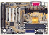
ATX POWER 7IX Motherboard 7IX Motherboard Layout PS/2 JP2 USB JP10 AMD751 J9 AGP PCI1 7IX PCI2 PCI3 BIOS PCI4 PCI5 ISA1 ISA2 JP1 JP3 AMD756 BZ1 JP9 JP4 JP5 BAT1 J6 5 - Gigabyte GA-7IX | User Manual - Page 14
7IX Motherboard Layout 6 - Gigabyte GA-7IX | User Manual - Page 15
7IX Motherboard $ Page index for Connectors / Panel and Jumper Definition Page Connectors P.7 COMA / COMB / LPT Port P.7 USB Connector P.7 PS/2 Keyboard & PS/2 Mouse Connector P.8 PWR FAN P.8 CPU - Gigabyte GA-7IX | User Manual - Page 16
- Gigabyte GA-7IX | User Manual - Page 17
7IX Motherboard Connectors COM A / COM B / LPT Port LPT PORT COM A COM B USB Connector 5 6 78 12 34 Pin No. 1 2 3 4 5 6 7 8 Definition USB V0 USB D0USB D0+ GND USB V1 USB D1USB D1+ GND 7 - Gigabyte GA-7IX | User Manual - Page 18
PS/2 Keyboard & PS/2 Mouse Connector Connectors PS/2 Mouse PS/2 Mouse/ Keyboard Pin No. Definition 1 6 5 2 4 3 3 Data NC GND 2 1 4 PS/2 Keyboard 5 6 VCC(+5V) Clock NC POWER FAN 1 Pin No. Definition 1 GND 2 +12V 3 SENSE 8 - Gigabyte GA-7IX | User Manual - Page 19
7IX Motherboard CPU FAN SYSTEM FAN Pin No. Definition 1 1 2 GND +12V 3 SENSE 1 Pin No. Definition 1 GND 2 +12V 3 SENSE 9 - Gigabyte GA-7IX | User Manual - Page 20
ATX PWR FLOPPY Connectors 10 20 Pin No. Definition 3,5,7,13,15-17 GND 1,2,11 3.3V 4,6,19,20 VCC 10 +12V 12 -12V 18 1 11 8 -5V Power Good 9 5V SB stand by+5V 14 PS-ON(Soft On/Off) RED LINE 10 - Gigabyte GA-7IX | User Manual - Page 21
7IX Motherboard IDE1(Primary) , IDE2 (Secondary) USB : USB Port RED LINE IDE 1 IDE 2 Pin No. Definition 1 VCC 2 USB D0− 3 USB D0+ 1 4 GND 5 VCC 6 USB D1− 7 USB D1+ 8 GND 11 - Gigabyte GA-7IX | User Manual - Page 22
IR : Infrared Connector (Optional) Connectors Pin No. Definition 1 IR Data Output 1 2 GND 3 IR Data Input 4 NC 5 POWER (+) 12 - Gigabyte GA-7IX | User Manual - Page 23
7IX Motherboard Panel and Jumper Definition J22 : For 2X11 PINs Jumper 1 1 P−P−P+ HD J22 1 1 PW RE GD GN (Green Switch) GD (Green LED) HD (IDE Hard Disk - Gigabyte GA-7IX | User Manual - Page 24
JP10 : Keyboard Power On Panel and Jumper Definition Pin No. Definition 1 1-2 close Keyboard Power on Enabled 2-3 close Keyboard Power on Disabled (Default) JP1 : CASE OPEN Pin No. Definition 1 1 Signal 2 GND 14 - Gigabyte GA-7IX | User Manual - Page 25
7IX Motherboard JP3 : CLEAR CMOS Function 1 Pin No. Definition 1-2 close Clear CMOS (User had to short 1-2 till boot) 2-3 close Normal (Default) JP9 : RING PWR ON (Internal Modem Card Wake Up) Pin No. Definition 1 1 Signal 2 GND 15 - Gigabyte GA-7IX | User Manual - Page 26
JP4 : Wake on LAN Panel and Jumper Definition Pin No. Definition 1 +5VSB 1 2 GND 3 Signal JP5 : Internal Buzzer Connector (Optional) Pin No. Definition Close On board 1 speaker Enabled Open On board speaker Disabled 16 - Gigabyte GA-7IX | User Manual - Page 27
7IX Motherboard BAT1 : Battery + Danger of explosion if battery is incorrectly replaced. + Replace only with the same or + equivalent type recommended by the manufacturer. + Dispose of used batteries according to the manufacturer's instructions. 17 - Gigabyte GA-7IX | User Manual - Page 28
Panel and Jumper Definition 18 - Gigabyte GA-7IX | User Manual - Page 29
- Gigabyte GA-7IX | User Manual - Page 30
AMD AthlonTM processor • DRAM (128x1) MB SDRAM (LGS GM72V66841ET7J 9908 AA05) • CACHE SIZE • DISPLAY • STORAGE • O.S. • DRIVER 512 KB included in CPU GA-630 16MB SGRAM Onboard IDE (IBM DJNA-371800) Windows NT™ 4.0 SPK5 Display Driver at 1024 x 768 x 64k colors x 75Hz. Processor Winbench99 CPU - Gigabyte GA-7IX | User Manual - Page 31
7IX Motherboard Block Diagram 14.318MHz AGP AGP Bus SLOT A 3.3V SDRAM DIMM Sockets Host Bus AMD 100 MHz 100 MHz 33MHz 751 66MHz 100 MHz - Gigabyte GA-7IX | User Manual - Page 32
two notch. Memory size can vary between sockets. Install memory in any combination table: DIMM Bank 0 Bank 1 Bank 2 168-pin SDRAM DIMM Modules Supports 8 / 16 / 32 / 64 / 128 / 256 MB Supports 8 / 16 / 32 / 64 / 128 / 256 MB Supports 8 / 16 / 32 / 64 / 128 / 256 MB X 1 pcs X 1 pcs X 1 pcs 20 - Gigabyte GA-7IX | User Manual - Page 33
7IX Motherboard $ Page index for BIOS Setup Page The MAIN MENU P.23 Standard CMOS Features P.26 Advanced BIOS Features P.30 Advanced Chipset Features P.34 Integrated Peripherals P. - Gigabyte GA-7IX | User Manual - Page 34
BIOS Setup BIOS Setup BIOS Setup is an overview of the BIOS Setup Program. The program that allows users to modify the basic system configuration. This type of information is stored in battery-backed CMOS SRAM so that it retains the Setup information when the power is turned off. ENTERING SETUP - Gigabyte GA-7IX | User Manual - Page 35
7IX Motherboard GETTING HELP Main Menu The on-line description of the highlighted setup function is displayed at the bottom of the screen. Status Page Setup - Gigabyte GA-7IX | User Manual - Page 36
• Standard CMOS Features BIOS Setup This setup page includes all the items in standard compatible BIOS. • Advanced BIOS Features This setup page includes all the items of Award special enhanced features. • Advanced Chipset Features This setup page includes all the items of chipset special - Gigabyte GA-7IX | User Manual - Page 37
7IX Motherboard • Save & Exit Setup Save CMOS value settings to CMOS and exit setup. • Exit Without Saving Abandon all CMOS value changes and exit setup. 25 - Gigabyte GA-7IX | User Manual - Page 38
Date (mm:dd:yy) Time (hh:mm:ss) 4IDE Primary Master 4IDE Primary Slave 4IDE Secondary Master 4IDE Secondary Slave Drive A Drive B Floppy 3 Mode Support Thu , Jan 7 1999 2 : 31 : 24 Press Enter None Press Enter None Press Enter None Press Enter None 1.44M, 3.5 in. None Disabled Item Help Menu - Gigabyte GA-7IX | User Manual - Page 39
7IX Motherboard • Time The times format in . The time is to F that has been installed in the computer. There are two types: auto type, and manual type. Manual type is userdefinable; Auto type which will automatically detect HDD type. Note that the specifications of your - Gigabyte GA-7IX | User Manual - Page 40
category detects the type of adapter used for the primary system monitor that must match your video display card and monitor. Although secondary monitors are supported, you do not have to select the type in setup. EGA/VGA CGA 40 CGA 80 MONO Enhanced Graphics Adapter/Video Graphics Array. For EGA - Gigabyte GA-7IX | User Manual - Page 41
7IX Motherboard • Memory The category is display-only which is determined by POST (Power On Self Test) of the BIOS. Base Memory The POST of the - Gigabyte GA-7IX | User Manual - Page 42
. The system will halt and the following error message will appear in the mean time. You can run anti-virus program to locate the problem. Enabled Disabled Activate automatically when the system boots up causing a warning message to appear when anything attempts to access the boot sector or hard - Gigabyte GA-7IX | User Manual - Page 43
7IX Motherboard • CPU Internal Cache / External Cache These two categories speed up memory access. However, it depends on CPU / chipset design. Enabled Disabled Enable cache function. ( - Gigabyte GA-7IX | User Manual - Page 44
• Boot Up Floppy Seek BIOS Setup During POST, BIOS will determine the floppy disk drive installed is 40 or 80 tracks. 360 K type is 40 tracks 720 K, 1.2 M and 1.44 M are all 80 tracks. Enabled Disabled BIOS searches for floppy disk drive to determine it is 40 or 80 tracks. Note that BIOS can not - Gigabyte GA-7IX | User Manual - Page 45
7IX Motherboard • OS Select For DRAM>64MB Non-OS2 OS2 Using non-OS2 operating system. ( Default value ) Using OS2 operating system and DRAM>64MB. • HDD S.M.A.R.T. Capability - Gigabyte GA-7IX | User Manual - Page 46
Advanced Chipset Features BIOS Setup CMOS Setup Utility-Copyright( C ) 1984-1999 Award Software Advanced Chipset Features System BIOS Cacheable Video RAM Cacheable Memory Hole At 15M−16M AGP Aperture Size (MB) K7 CLK_CTL Select SDRAM ECC Setting SDRAM PH Limit SDRAM Idle Limit SDRAM Timing - Gigabyte GA-7IX | User Manual - Page 47
7IX Motherboard • AGP Aperture Size (MB) 32 Set AGP Aperture Size to 32. 64 Set AGP Aperture Size to 64. ( Default value ) 128 Set AGP Aperture - Gigabyte GA-7IX | User Manual - Page 48
Set SDRAM Timing Configuration to Auto. ( Default value ) Set SDRAM Timing Configuration to Manual. • SDRAM Trc Timing Value This function specify the minimum time from activate to activate of the same bank. 3 Cycle 4 Cycle 5 Cycle 6 Cycle 7 Cycle 8 Cycle Set - Gigabyte GA-7IX | User Manual - Page 49
7IX Motherboard • SDRAM Trcd Timing Value This function specify the delay from the activation of a bank to the time that a read or write command is accepted. 1 - Gigabyte GA-7IX | User Manual - Page 50
UDMA On-Chip Primary PCI IDE On-Chip Secondary PCI IDE USB Host Controller USB keyboard Support Init Display First IDE HDD Block Mode POWER ON Function * KB Power ON Password Onboard BIOS will automatically detect the IDE HDD Accessing mode. ( Default value ) Manually set the IDE Accessing mode. 38 - Gigabyte GA-7IX | User Manual - Page 51
7IX Motherboard • IDE Primary Slave PIO (for onboard IDE 1st channel) Auto Mode0~4 BIOS will automatically detect the IDE HDD Accessing mode. ( Default value ) Manually set the IDE Accessing mode. • IDE Secondary Master PIO (for onboard IDE 2nd channel) Auto Mode0~4 BIOS will automatically - Gigabyte GA-7IX | User Manual - Page 52
Controller Enabled Disabled Enable USB Host Controller. ( Default value ) Disable USB Host Controller. • USB Keyboard Support Enabled Disabled Enable USB Keyboard Support. Disable USB Keyboard Support. ( Default value ) • Init Display First PCI Slot AGP Set Init Display First to PCI Slot - Gigabyte GA-7IX | User Manual - Page 53
7IX Motherboard • Onboard Serial Port 1 Auto 3F8/IRQ4 2F8/IRQ3 3E8/IRQ4 2E8/IRQ3 Disabled BIOS will automatically setup the port 1 address. Enable onboard Serial port 1 - Gigabyte GA-7IX | User Manual - Page 54
IRQ9 (IRQ2 Redir) IRQ10 (Reserved) IRQ11 (Reserved) IRQ12 (PS/2 Mouse) IRQ13 (Coprocessor) IRQ14 (Hard Disk) IRQ15 ( Reserved) User Define DPMS Support PwrOn Suspend Disabled Disabled Disabled Instant-off Soft-Off Disabled Disabled NA Disabled 0 0 0 0 Enabled Enabled Enabled Enabled Enabled Enabled - Gigabyte GA-7IX | User Manual - Page 55
7IX Motherboard • Power Management User Define Min Saving Max Saving For configuring our own power management features. ( Default value ) Enable Green function. Disable Green function. • Video off Method V/H SYNC+Blank Blank Screen DPMS Support BIOS will turn off V/H-SYNC when gets into Green - Gigabyte GA-7IX | User Manual - Page 56
• AC Back Function BIOS Setup Memory Soft-Off Full-On This function depends on computer status. Set System Soft-Off Status. ( Default value ) Set System Full-On Status. • Wake-Up by PCI card Disabled Enabled Disabled this function. ( Default value ) Enabled wake-up by PCI card. • ModemRingOn - Gigabyte GA-7IX | User Manual - Page 57
7IX Motherboard • Secondary IDE 0/1 Disabled Enabled Disable this function. Enable monitor Secondary IDE 0/1 for Green event. ( Default value ) • Parallel Port Disabled Enabled Disabled this function. Enabled - Gigabyte GA-7IX | User Manual - Page 58
value ) • Reset Configuration Data Disabled Enabled Disable this function. ( Default value ) Enable clear PnP information in ESCD. • Resources Controlled by Manual Auto(ESCD) User can set the PnP resource (I/O Address, IRQ & DMA channels) used by legacy ISA DEVICE. BIOS automatically use these - Gigabyte GA-7IX | User Manual - Page 59
7IX Motherboard • IRQ ( 3,4,5,7,9, 10,11,12,14,15 ),DMA( 0,1,3,5,6,7 ) assigned to ( Legacy ISA or "PCI/ISA PnP ) Legacy ISA The resource is used by Legacy ISA - Gigabyte GA-7IX | User Manual - Page 60
PC Health Status BIOS Setup CMOS Setup Utility-Copyright( C ) 1984-1999 Award Software PC Health Status Reset Case Open Status Case Opened Shutdown Temperature CPU Warning Temperature CPU FAN Fail Alarm System FAN Fail Alarm Power FAN Fail Alarm Current System Temp. Current CPU Temperature CPU - Gigabyte GA-7IX | User Manual - Page 61
7IX Motherboard • Shutdown Temp. (°C / °F) (This function will be effective only for the operating systems that support ACPI Function.) Disabled 65°C / 149°F 70°C / 158°F 75°C / 167°F Normal Operation Monitor CPU Temp. at 65°C / 149°F, if Temp. > 65°C / 149°F system will automatically power - Gigabyte GA-7IX | User Manual - Page 62
Load Fail-Safe Defaults BIOS Setup CMOS Setup Utility-Copyright( C ) 1984-1999 Award Software 4Standard CMOS Features Load Fail-Safe Defaults 4Advanced BIOS Features Load Optimized Defaults 4Advanced Chipset Features Set Supervisor Password 4Integrated Peripherals Set User Password 4Power - Gigabyte GA-7IX | User Manual - Page 63
7IX Motherboard Load Optimized Defaults CMOS Setup Utility-Copyright( C ) 1984-1999 Award Software 4Standard CMOS Features Load Fail-Safe Defaults 4Advanced BIOS Features Load Optimized Defaults - Gigabyte GA-7IX | User Manual - Page 64
BIOS Setup Set Supervisor / User Password When you select this function, the following message will appear at the center of the screen to assist you in creating a password. CMOS Setup Utility-Copyright( C ) 1984-1999 Award Software 4Standard CMOS Features Load Fail-Safe Defaults 4Advanced BIOS - Gigabyte GA-7IX | User Manual - Page 65
7IX Motherboard Save & Exit Setup CMOS Setup Utility-Copyright( C ) 1984-1999 Award Software 4Standard CMOS Features Load Fail-Safe Defaults 4Advanced BIOS Features Load Optimized Defaults - Gigabyte GA-7IX | User Manual - Page 66
Exit Without Saving BIOS Setup CMOS Setup Utility-Copyright( C ) 1984-1999 Award Software 4Standard CMOS Features Load Fail-Safe Defaults 4Advanced BIOS Features Load Optimized Defaults 4Advanced Chipset Features Set Supervisor Password 4Integrated Peripherals Set User Password 4Power - Gigabyte GA-7IX | User Manual - Page 67
7IX Motherboard Appendix Acronyms Acro. Meaning ACPI Advanced configuration and power interface POST channel interface card enhanced SCI Special A.G.P. Accelerated circumstance graphics port instructions LBA Logical block S.E.C.C Single edge addressing . contact cartridge EMC - Gigabyte GA-7IX | User Manual - Page 68
Acro. Meaning DRM Dual retention mechanism ISA Industry standard architecture Acro. Meaning PAC PCI A.G.P. controller AMR Audio Modem Riser Appendix continued Acro. Meaning PCI Peripheral component interconnect 56
-
 1
1 -
 2
2 -
 3
3 -
 4
4 -
 5
5 -
 6
6 -
 7
7 -
8
-
9
-
10
-
11
-
12
-
13
-
14
-
15
-
16
-
17
-
18
-
19
-
20
-
21
-
22
-
23
-
24
-
25
-
26
-
27
-
28
-
29
-
30
-
31
-
32
-
33
-
34
-
35
-
36
-
37
-
38
-
39
-
40
-
41
-
42
-
43
-
44
-
45
-
46
-
47
-
48
-
49
-
50
-
51
-
52
-
53
-
54
-
55
-
56
-
57
-
58
-
59
-
60
-
61
-
62
-
63
-
64
-
65
-
66
-
67
-
68
 |
 |

FCC Compliance Statement:
This equipment has been tested and found to
comply with limits for a Class B digital device ,
pursuant to Part 15 of the FCC rules. These
limits are designed to provide reasonable
protection
against
harmful
interference
in
residential
installations.
This
equipment
generates,
uses,
and
can
radiate
radio
frequency energy, and if not installed and used
in accordance with the instructions, may cause
harmful interference to radio communications.
However,
there
is
no
guarantee
that
interference will not occur in a particular
installation. If this equipment does cause
interference to radio or television equipment
reception, which can be determined by turning the equipment off and on, the
user is encouraged to try to correct the interference by one or more of the
following measures:
-Reorient or relocate the receiving antenna
-Move the equipment away from the receiver
-Plug the equipment into an outlet on a circuit different from that to which
the receiver is connected
-Consult the dealer or an experienced radio/television technician for
additional suggestions
You are cautioned that any change or modifications to the equipment not
expressly approve by the party responsible for compliance could void Your
authority to operate such equipment.
This device complies with Part 15 of the FCC Rules. Operation is subjected to
the following two conditions 1) this device may not cause harmful interference
and 2) this device must accept any interference received, including
interference that may cause undesired operation.
DECLARATION OF CONFORMITY
Per FCC Part 2 Section 2. 1077(a)
Responsible Party Name: G.B.T. INC.
Address: 18305 Valley Blvd., Suite#A
LA Puent, CA 91744
Phone/Fax No: (818) 854-9338/ (818) 854-9339
hereby declares that the product
Product Name:
Model Number:
Mother Board
Conforms to the following specifications:
FCC Part 15, Subpart B, Section 15.107(a) and Section 15.109(a),
Class B Digital Device
Supplementary Information:
This device complies with part 15 of the FCC Rules. Operation is subject to the
following two conditions:
(1)
This device may not cause harmful
and
(2)
this device must accept any inference received, including
that may cause undesired operation.
Representative Person's Name:
ERIC LU
Signature:
Date:
Aug. 4, 1999
Eric
Eric Lu
Lu
GA-7IX