Gigabyte GA-7VAX-A User Manual
Gigabyte GA-7VAX-A Manual
 |
View all Gigabyte GA-7VAX-A manuals
Add to My Manuals
Save this manual to your list of manuals |
Gigabyte GA-7VAX-A manual content summary:
- Gigabyte GA-7VAX-A | User Manual - Page 1
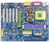
is compatible with 2X(3.3V)/4X(1.5V) modeAGP slot, but they support 2X(3.3V) only. The GA-7VAX-A/ GA-7VAX1394-A / GA-7VAXP-A/ GA-7VAXP-A Ultra motherboards might not function properly, If you install this card in it. Note : Although Gigabyte's AG32S(G) graphics card is based on ATi Rage 128 Pro chip - Gigabyte GA-7VAX-A | User Manual - Page 2
M The author assumes no responsibility for any errors or omissions that may appear in this document nor does the author make a commitment to update the information contained herein. M Third-party brands and names are the property of their respective owners. M Please do not remove any labels on - Gigabyte GA-7VAX-A | User Manual - Page 3
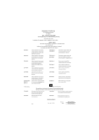
550 14 o EN 550 15 o EN 550 20 T EN 550 22 o D IN VDE 08 55 o part 10 o part 12 Mother Boa rd GA-7VAX-A / GA-7VAX1394-A / G A-7VAXP-A / GA-7VAXP-A Ultra is in conformity with (reference to the specification under w hich conformity is declared) in accordance with 89/336 E EC-EMC Directive Li mits - Gigabyte GA-7VAX-A | User Manual - Page 4
, CA 91748 Phone/FaxNo: (818) 854-9338/ (818) 854-9339 hereby declares that the product ProductName: Motherboard ModelNumber: GA-7VAX-A / GA-7VAX1394-A / GA-7VAXP-A / GA-7VAXP-A Ultra Conforms to the following specifications: FCC Part 15, Subpart B,Section 15.107(a) and Section 15.109(a), Class - Gigabyte GA-7VAX-A | User Manual - Page 5
KT400A Series AMD Socket A Processor Motherboard USER'S MANUAL AMD Athlon™ / Athlon™ XP / Duron™ SocketAProcessor Motherboard Rev. 1002 12ME-7VAXPAU-1002 - Gigabyte GA-7VAX-A | User Manual - Page 6
English Table of Content Item Checklist 4 WARNING 4 Chapter 1 Introduction 5 Features Summary 5 KT400A Series Motherboard Layout 8 Block Diagramt 9 Chapter 2 Hardware Installation Process 11 Step 1: Install the Central Processing Unit (CPU 12 Step1-1: CPU Speed Setup 12 Step1-2: CPU - Gigabyte GA-7VAX-A | User Manual - Page 7
English Power Management Setup 48 PnP/PCI Configurations 51 PC Health Status 52 Frequency/Voltage Control 54 Top Performance 56 Load Fail-Safe Defaults 57 Load Optimized Defaults 58 Set Supervisor/User Password 59 Save & Exit Setup 60 Exit Without Saving 61 Chapter 4 Technical Reference - Gigabyte GA-7VAX-A | User Manual - Page 8
*** o SPD Kit x1 þ Quick PC Installation Guide þ SATA RAID Manual * o GC-SATA Card * (Optional) (Manual ; SATAcable x1 ; Powercable x 1) Computer motherboards * " FOR GA-7VAXP-A Ultra Only. " ** " FOR GA-7VAXP-A Ultra / GA-7VAXP-A Only. " *** " For GA-7VAXP-A Ultra / GA-7VAXP-A / GA-7VAX1394-A Only. - Gigabyte GA-7VAX-A | User Manual - Page 9
size form factor, 4 layers PCB. - KT400A Series: GA-7VAX-A / GA-7VAX1394-A / GA-7VAXP-A / GA-7VAXP Ultra-A - Socket A processor AMD AthlonTM/AthlonTM XP/ DuronTM (K7) 128KL1 & 512K/256K/64K L2 cache on die 200/266/333MHz FSB and DDRbus speeds - Supports 1.4GHz and faster - VIA KT400A Memory/AGP/PCI - Gigabyte GA-7VAX-A | User Manual - Page 10
or DISK Mirroring (RAID1) - Supports UDMA up to 150 MB/sec - AIL UDMA and PIO Modes - Up to 2 SATA Device - ACPI and ATA/ATAPI6 " * " FOR GA-7VAXP-A Ultra Only. " ** " FOR GA-7VAXP-A Ultra / GA-7VAXP-A Only. " *** " For GA-7VAXP-A Ultra / GA-7VAXP-A / GA-7VAX1394-A Only. KT400A Series Motherboard - Gigabyte GA-7VAX-A | User Manual - Page 11
- Wake on LAN (WOL) - AC Recovery - Poly fuse for keyboard over-current protection - USB KB/Mouse wake up from S3 - SupportThermal shutdown function - Supports @BIOS - Supports EasyTune 4 - Over Voltage (DDR/AGP/CPU) by BIOS - Over Clock (DDR/AGP/CPU/PCI) by BIOS Please setthe CPU host frequency in - Gigabyte GA-7VAX-A | User Manual - Page 12
BIOS S_ATA 2* S_ATA 1* SPDIF_IN WO L PWR_LED F_PAN EL F1_1394 F2_1394 F3-1394 F_U SB1 F_U SB2 IEEE 1394 *** USB 2.0 " * " FOR GA-7VAXP-A Ultra Only. " ** " FOR GA-7VAXP-A Ultra / GA-7VAXP-A Only. " *** " For GA-7VAXP-A Ultra / GA-7VAXP-A / GA-7VAX1394-A Only. KT400A Series Motherboard - 8 - - Gigabyte GA-7VAX-A | User Manual - Page 13
) CLK HCLK+/- (100/133/166MHz) CPUCLK+/- (100/133/166MHz) 14.318 M Hz 33 M Hz GEN AGPCLK (66MHz) V_Link (66MHz) " * " FOR GA-7VAXP-A Ultra Only. " ** " FOR GA-7VAXP-A Ultra / GA-7VAXP-A Only. " *** " For GA-7VAXP-A Ultra / GA-7VAXP-A / GA-7VAX1394-A Only. - 9 - Hardware Installation Process - Gigabyte GA-7VAX-A | User Manual - Page 14
English KT400A Series Motherboard - 10 - - Gigabyte GA-7VAX-A | User Manual - Page 15
English Chapter 2 Hardware Installation Process To set up your compute r, you must complete the following steps: Step 1- Set Dip Switch (CK_RATIO) and system Switch (SW1) Ste p 2- Install the Central Processing Un it (CPU) Step 3- Install memory modules Step 4- Install expansion cards Step 5- - Gigabyte GA-7VAX-A | User Manual - Page 16
English Step 1: Install the Central Processing Unit (CPU) Step1-1: CPU Speed Setup The clock ratio can be switched by CK_RATIO and refer to below table. CLK_RATIO O: ON / X :OFF RATIO 1 2 3 4 56 AUTO X X X X XX (De fault) 5x O O X O OO 5.5x X O X O OO 6x O X X O OO 6.5x X X X O OO - Gigabyte GA-7VAX-A | User Manual - Page 17
English Step1-2: CPU Installation Before installing the processor, adhere to the following warning: 1.Please make sure the CPU type is supported by the motherboard. 2.If you do not match the CPU socket Pin 1 and CPU cut edge well, it will cause improper installation. Please change the - Gigabyte GA-7VAX-A | User Manual - Page 18
, this completes the installation. Please refer to CPU cooling fan user's manual for more detailinstallation procedure. 1. Press down the CPU socket lever and 2. Use qualified fan approved by AMD. 3. Fasten the cooling fan supporting-base onto the CPU socket on the mainboard. 4. Make sure the - Gigabyte GA-7VAX-A | User Manual - Page 19
into the DIMM Slot. The DIMM module can only fit in one d irection due to the notch. Memory size can vary between sockets. Notch DDR Support Unbuffered DDR DIMM Sizes type: 64 Mbit (2Mx8x4 banks) 64 Mbit (1Mx16x4 banks) 128 Mbit(2Mx16x4 banks) 256 Mbit(8Mx8x4 banks) 512 Mbit(16Mx8x4 banks - Gigabyte GA-7VAX-A | User Manual - Page 20
bandwidth. DDR SDRAM will offer a superior solution and m igration path from existing SDRAM designs due to its availability, pricing and overall market support. PC2100 DDR memory (DDR266) doubles the data rate through reading and writing at both the rising and falling edge of the clock, achieving - Gigabyte GA-7VAX-A | User Manual - Page 21
English Step 3: Install expansion cards 1. Read the related expansion card's instruction document before install the expansion card into the computer. 2. Remove your computer's chassis cover,necessary screws and slotbracketfrom the computer. 3. Press the expansion card firmly - Gigabyte GA-7VAX-A | User Manual - Page 22
(s), please ma ke sure your device(s) such as USB keyboard, mouse, scanner, zip, speaker..etc. Have a standard USB interface. Also make sure your OS supports USB con troller. If your OS d oes n ot sup port USB controller, please contactOS vendor for possible pa tch or driver upgrad e. For more info - Gigabyte GA-7VAX-A | User Manual - Page 23
d to Parallelport;mouse andmodem etc can be connected to Serial ports. COMA COMB Serial Ports (9 pin Male) x Game /MIDI Ports Ø This connector supports joystick, MIDI keyboard and other relate audio devices. Joystick/ MIDI (15 pin Female) y Audio Connectors Line Out (Front Speaker) MIC In - Gigabyte GA-7VAX-A | User Manual - Page 24
CD_IN 17) AUX_IN 18) SPDIF_O 19) SPDIF-IN 20) IR 21) F_USB1/F_USB2 22) F1_1394/F2_1394/F3_1394*** 23) WOL 24) SCR 25) CI " * " FOR GA-7VAXP-A Ultra Only. " ** " FOR GA-7VAXP-A Ultra / GA-7VAXP-A Only. " *** " For GA-7VAXP-A Ultra / GA-7VAXP-A / GA-7VAX1394-A Only. KT400A Series Motherboard - 20 - - Gigabyte GA-7VAX-A | User Manual - Page 25
CPU co oler is esse ntial to prevent th e CPU from running under abnormal condition or damaged by overheating.The CPU fan connector supports Max. currentup to 600 mA. 1 PinNo. Definition 1 GND 2 +12V 3 Sense 2) SYS_FAN (System FAN Connector) This connector allows you to link with the cooling - Gigabyte GA-7VAX-A | User Manual - Page 26
English 3) PWR_FAN (Power Fan Connector) This connector allows you to link with the cooling fan on the system case to lower the system tem peratu re. PinNo. Definition 1 1 GND 2 +12V 3 Sense 4) NB_FAN If you installed wrong direction, the Chip Fan will not work. Sometimes will damage the Chip - Gigabyte GA-7VAX-A | User Manual - Page 27
Serial ATA device to this connector, it provides you high speed transfer rates (150MB/sec). PinNo. Definition 1 GND 2 TXP 7 1 3 TXN 4 GND 5 RXN 6 RXP 7 GND " * " FOR GA-7VAXP-A Ultra Only. - 23 - Hardware Installation Process - Gigabyte GA-7VAX-A | User Manual - Page 28
operation. For details, please refer to the RAID manual. 40 39 2 1 IDE4 (BIOS Default Value :ATA, If you want to use RAID function, please change "Integrated Peripherals-RAID Controller Function "to "RAID") " ** " FOR GA-7VAXP-A Ultra / GA-7VAXP-A Only. KT400A Series Motherboard - 24 - - Gigabyte GA-7VAX-A | User Manual - Page 29
English 9) FDD(Floppy Connector) Please connect the floppy drive ribbon cables to FDD. Itsupports 360K,720K,1.2M,1.44M and 2.88Mbytes floppy disk types. The red stripe of the ribbon cable must be the same side with the Pin1. 34 33 2 1 10) RAM_LED Do n ot remove memory modules while RAM LED is - Gigabyte GA-7VAX-A | User Manual - Page 30
English 11) F_PANEL (2x10 pins connector) Please connect the po wer LED, PC peaker, rese t switch and power switch etc of your chassis frontpanel to the F_PANEL connector according to the pin assignment above. Me ssa g e LED/Po we r / Sleep LED Soft Po wer Connector Speaker Connector MSGMSG+ - Gigabyte GA-7VAX-A | User Manual - Page 31
with the same or equivalent type recommended by the manufacturer. v Dispose of used batteries according to the If you want to erase CMOS... manufacturer's instructions. 1.Turn OF F the computer and unplug the power cord. 2.Re move th e battery, wa it for 30 second. 3.Re-install the battery - Gigabyte GA-7VAX-A | User Manual - Page 32
English 15) SUR_CEN Please contact your ne arest dea ler for o ptional SUR_CEN cable. PinNo. Definition 65 1 SUROUTL 2 SUROUTR 3 GND 4 NoPin 21 5 CENTER_OUT 6 BASS_OUT 16) CD_IN (CD IN) Connect CD-ROM or DVD-ROM audio outto the connector. PinNo. Definition 1 CD-L 1 2 GND 3 GND 4 CD_R - Gigabyte GA-7VAX-A | User Manual - Page 33
English 17) AUX_IN ( AUX In Connector) Connect other device(such as PCITV Tunner audio out)to the connector. PinNo. Definition 1 AUX-L 1 2 GND 3 GND 4 AUX_R 18) SPDIF_O (SPDIFOut) The SPDIF outputis capable of providing digital audio to external speakers or compressed AC3 data to an extern al - Gigabyte GA-7VAX-A | User Manual - Page 34
English 19) SPDIF_IN Use this feature only when your device has digital output function. Pin No. Definition 1 1 VCC 2 SPDIF IN 3 GND 20) IR Be careful with the polarity o f the IR conn ectorwhile yo u conn ect the IR. Please contact you nearest de aler for optional IR device. 1 5 Pin No. - Gigabyte GA-7VAX-A | User Manual - Page 35
, high bandwidth and h ot plug. 2 10 19 Pin No. 1 2 3 4 5 6 7 8 9 10 Definition T PA+ T PAGND GND T PB+ T PBPower Power No Pin GND F1_1394 F2_1394 F3_1394 IEEE1394 *** " *** " For GA-7VAXP-A Ultra / GA-7VAXP-A / GA-7VAX1394-A Only. - 31 - Hardware Installation Process - Gigabyte GA-7VAX-A | User Manual - Page 36
PinNo. Definition 1 +5V SB 2 GND 3 Signal 24) SCR (Smart Card Reader Header,Black Connector) This MB supports smartcard reader. To enable smartcard reader function an optional smart card reader box is require d. Please contact yo ur autherized distributor. 6 10 15 Pin No. 1 2 3 4 5 6 7 8 9 - Gigabyte GA-7VAX-A | User Manual - Page 37
English 25) CI (CASE OPEN) This 2 pin connector allows your system to enable or disable the "case open"item in BIOS if the system ca se beg in remove. PinNo. Definition 1 1 Signal 2 GND - 33 - Hardware Installation Process - Gigabyte GA-7VAX-A | User Manual - Page 38
English KT400A Series Motherboard - 34 - - Gigabyte GA-7VAX-A | User Manual - Page 39
English Chapter 3 BIOS Setup BIOS Setup is an overview of the BIOS Setup Program. The program that allows users to modify the basic system configuration. This type of information is stored in battery-backed CMOS RAM so that it retains the Setup information when the power is turned off. ENTERING S - Gigabyte GA-7VAX-A | User Manual - Page 40
English GETTING HELP Mai n Menu The on-line description of the highlighted setup function is displayed at the bottom of the screen. Status Page Setup Menu / Option Pag e S etup Menu Press F1 to pop up a small help window that describes the appropriate keys to use and the possible selections for the - Gigabyte GA-7VAX-A | User Manual - Page 41
English l Power Manag ement Setup This setup page includes all the items of Green function features. l PnP/PCI Configurations This setup page includes all the configurations of PCI & PnP ISA resources. l PC Health Status This setup page is the System auto detect Temperature, voltage, fan, speed. l - Gigabyte GA-7VAX-A | User Manual - Page 42
2002 Item Help Time (hh:mm:ss) }IDE Primary Master }IDE Primary Slav e }IDE Secondary Master }IDE Secondary Slav e Driv e A Driv e B Floppy 3 Mode Support 22:31:24 [Press Enter None] [Press Enter None] [Press Enter None] [Press Enter None] [1.44M, 3.5"] [None] [Disabled] Menu Lev el u Change the - Gigabyte GA-7VAX-A | User Manual - Page 43
identifies the types of hard disk from drive C to F that has been installed in the computer. There are two types: auto type, and manual type. Manual type is user-definable; Auto type which will automatically detect HDD type. Note thatthe specifications of your drive must match with the drive - Gigabyte GA-7VAX-A | User Manual - Page 44
English FFloppy 3 Mode Support (for J apan Area) 8Disabled Normal Floppy Drive. (Default value) 8Drive A Enabled 3 mode function of Drive A. 8Drive B Enabled 3 mode function of Drive B. 8Both Drive A & B are 3 mode - Gigabyte GA-7VAX-A | User Manual - Page 45
-0~3 Select your boot device priority by HDD-0~3. 8SC SI Select your boot device priority by SCSI. 8CDROM Select your boot device priority by CDROM. " * " FOR GA-7VAXP-A Ultra Only. " ** " FOR GA-7VAXP-A U ltra / GA-7VAXP-A Only. - 41 - BIOS Setup - Gigabyte GA-7VAX-A | User Manual - Page 46
Automatically set AGP transfer rate according to AGP compatibility and stability. (Default value) 88X Always set AGP transfer rate to 8X if the 8X mode supported by the AGP card. 84X Set AGP transfer rate to 4X mode no matter what the AGP transfer rate the card is. FInit Display First - Gigabyte GA-7VAX-A | User Manual - Page 47
AC97 Audio USB 1.1 Controller USB 2.0 Controller USBKey board Support USBMouse Support OnboardH/W LAN [Enabled] [Auto] [Auto] [Enabled] Peripherals " * " FOR GA-7VAXP-A Ultra Only. " ** " FOR GA-7VAXP-A U ltra / GA-7VAXP-A Only. " *** " For GA-7VAXP-A Ultra / GA-7VAXP-A / GA-7VAX1394-A Only. - 43 - Gigabyte GA-7VAX-A | User Manual - Page 48
English FOnChip IDE Channel0 M When enabled, allows you to use the onboard primary PCI IDE. If a hard disk controller card is used, set at Disabled. 8Enabled Enable onboard 1st channel IDE port. (Default value) 8Disabled Disable onboard 1st channel IDE port. FOnChip IDE Channel1 M When enabled, - Gigabyte GA-7VAX-A | User Manual - Page 49
Support. 8Disabled Disabled USB Keyboard Support. (Default value) FUSB Mouse Support 8Enabled Enabled USB Mouse Support. 8Disabled Disabled USB Mouse Support * " FOR GA-7VAXP-A Ultra Only. " ** " FOR GA-7VAXP-A U ltra / GA-7VAXP-A Only. " *** " For GA-7VAXP-A Ultra / GA-7VAXP-A / GA-7VAX1394-A Only. - Gigabyte GA-7VAX-A | User Manual - Page 50
English FOnboard H/W Serial ATA * 8Enabled Enabled Onboard H/W Serial ATA support.(Default value) 8Disabled Disabled Onboard H/W Serial ATA . FSerial ATA Function * port. (Default Value) 8SC R Using as smart card Interface. " * " FOR GA-7VAXP-A Ultra Only. KT400A Series Motherboard - 46 - - Gigabyte GA-7VAX-A | User Manual - Page 51
. 8Disabled Disable onboard parallel port. FParallel Port Mode M This feature allows you to connect with an advanced print via the port mode it supports. 8SPP Using Parallel port as Standard Parallel Port using IRQ7. (Default Value) 8EPP Using Parallel port as Enhanced Parallel Port IRQ5. 8EC - Gigabyte GA-7VAX-A | User Manual - Page 52
English Power Management Setup CMOS Setup Utility -Copy right (C) 1984-2003 Aw ard Softw are Pow er Management Setup ACPI Suspend Ty pe [S1(POS)] øUSB Dev ice Wake-Up From S3 Disabled Pow er LED in S1 state [Blinking] Soft-Off by PWRBTN [Instant-off] AC Back Function [Soft-Off] - Gigabyte GA-7VAX-A | User Manual - Page 53
English FPower LED i n S1 state 8Blinking 8Dual/Off In standby mode(S1), power LED will blink. (Default Value) In standby mode(S1): a. If use single color LED, power LED will turn off. b. If use dual color LED, power LED will turn to another color. FSoft-off by PWRBTN 8Instant-off 8Delay 4 Sec. - Gigabyte GA-7VAX-A | User Manual - Page 54
English FPME Event Wake up M When set at Enabled, any PCI-PM event awakes the system from a PCI-PM controlled state. M This feature requires an ATX power supply that provides at least 1A on the +5VSB lead. 8Disabled Disabled PME Event Wake up function. 8Enabled Enabled PME Event Wake up - Gigabyte GA-7VAX-A | User Manual - Page 55
English PnP/PCI Configurations CMOS Setup Utility -Copy right (C) 1984-2003 Aw ard Softw are PnP/PCI Configurations PCI1/PCI5 IRQ Assignment [Auto] Item Help PCI2 IRQ Assignment PCI3IRQ Assignment PCI4IRQ Assignment [Auto] [Auto] [Auto] Menu Lev el u Dev ice(s) using this INT: RAID Cntrlr - Gigabyte GA-7VAX-A | User Manual - Page 56
English PC Health Status CMOS Setup Utility -Copy right (C) 1984-2003 Aw ard Softw are PC Health Status Reset Case Open Status [Disabled] Case Opened No VCORE 1.772V DDRVtt 1.248V +3.3V 3.280V + 5V 4.919 V +12V 11.968V 5VSB 5.053V Current Sy stem Temperature 31°C Current CPU - Gigabyte GA-7VAX-A | User Manual - Page 57
English FCurrent CPU FAN / SYSTEM FAN Speed (RPM) Detect Fan speed status automatically. F Fan Fail Warni ng ( CPU / SYSTEM) 8Disabled Don't monitor current fan speed. (Default value) 8Enabled Alarm when stops. FCPU Shutdown Temperature 8Enabled System shutdown when current CPU temperature - Gigabyte GA-7VAX-A | User Manual - Page 58
English Frequency/Voltage Control CMOS Setup Utility -Copy right (C) 1984-2003 Aw ard Softw are Frequency /Voltage Control Spread spectrum Modulated [Auto] CPU Host Clock Control [Disable] øCPU Host Frequency (MHz) 100 øPCI/AGP Frequency (MHz) 33/66 DRAM Clock(MHz) [By SPD] CPU Voltage - Gigabyte GA-7VAX-A | User Manual - Page 59
English FPCI/AGP Frequency (MHz) 8The values depend on CPU Host Frequency(Mhz) . FDRAMClock (MHz) M Wrong frequency may make system can't boot. Clear CMOS to overcome wrong frequency issue. 8Please set DRAM Clock according to your requirement. If you use DDR266 DRAM module, please set "DRAM - Gigabyte GA-7VAX-A | User Manual - Page 60
not run properly w ith Window s XP, but w orks smoothly w ith Window s NT. Therefore, if y our sy stem is not perform enough, the reliability or stability problem w ill appear sometimes, and w e w ill recommend y ou disabling the option to av oid the - Gigabyte GA-7VAX-A | User Manual - Page 61
English Load Fail-Safe Defaults CMOS Setup Utility -Copy right (C) 1984-2003 Aw ard Softw are }Standard CMOS Features Top Performance }Adv ancedBIOS Features Load Fail-Safe Defaults }Integrated Peripherals Load Optimized Defaults }Pow er Management Setup SetSuperv isor Password }PnP/PCI - Gigabyte GA-7VAX-A | User Manual - Page 62
English Load Optimized Defaults CMOS Setup Utility -Copy right (C) 1984-2003 Aw ard Softw are }Standard CMOS Features Top Performance }Adv ancedBIOS Features Load Fail-Safe Defaults }Integrated Peripherals Load Optimized Defaults }Pow er Management Setup SetSuperv isor Password }PnP/ - Gigabyte GA-7VAX-A | User Manual - Page 63
English Set Supervisor/User Password CMOS Setup Utility -Copy right (C) 1984-2003 Aw ard Softw are }Standard CMOS Features Top Performance }Adv ancedBIOS Features Load Fail-Safe Defaults }Integrated Peripherals Load Optimized Defaults }Pow er Management Setup SetSuperv isor Password }PnP/ - Gigabyte GA-7VAX-A | User Manual - Page 64
English Save & Exit Setup CMOS Setup Utility -Copy right (C) 1984-2003 Aw ard Softw are }Standard CMOS Features Top Performance }Adv ancedBIOS Features Load Fail-Safe Defaults }Integrated Peripherals Load Optimized Defaults }Pow er Management Setup SetSuperv isor Password }PnP/PCI - Gigabyte GA-7VAX-A | User Manual - Page 65
English Exit Without Saving CMOS Setup Utility -Copy right (C) 1984-2003 Aw ard Softw are }Standard CMOS Features Top Performance }Adv ancedBIOS Features Load Fail-Safe Defaults }Integrated Peripherals Load Optimized Defaults }Pow er Management Setup SetSuperv isor Password }PnP/PCI - Gigabyte GA-7VAX-A | User Manual - Page 66
English KT400A Series Motherboard - 62 - - Gigabyte GA-7VAX-A | User Manual - Page 67
English Chapter 4 Technical Reference BIOS Flash Procedure Method 1: We use GA-7VTX motherboard and Flash841 BIOS flash utility as example. Please flash the BIOS according to the following procedures if you are now under the DOS - Gigabyte GA-7VAX-A | User Manual - Page 68
English (2) Select the "Quick (erase)" for Format Type, and pick both "Display summary when finished" and "Copy system files", after that press "Start". That will format the floppy and transfer the needed system files to it. Beware: This procedure will erase all the prior data on that floppy, so - Gigabyte GA-7VAX-A | User Manual - Page 69
English STEP 3: Download BIOS and BIOS utility program. (1) Please go to Gigabyte website http://www.gigabyte.com.tw/index.html, and click "Support". (2) From Support zone, click the "Motherboards BIOS & Drivers". - 65 - Technical Reference - Gigabyte GA-7VAX-A | User Manual - Page 70
-7VTX motherboard as example. Please select GA-7VTX by Model or Chipset optional menu to obtain BIOS flash files. (4) Select an appropriate BIOS version (For example: F4), and click to download the - Gigabyte GA-7VAX-A | User Manual - Page 71
English (5) At this time the screen shows the following picture, please click "Extract" button to unzip the file s. (6) Please extract the download files into the clean bootable floppy disk A mentioned in STEP 2, and press "Extract". - 67 - Technical Reference - Gigabyte GA-7VAX-A | User Manual - Page 72
to enter BIOS setup main menu when system is boot up. Amer ican R el ea se :0 9/16 /9 9 Meg atre nd s AMIBIOS (C ) 1 99 9 Amer ica n Me ga tr en d 7VTX F1 Che ck Syste m He alth OK AMD -Athlo n(tm)Processor-900 MHz Ch ecking NVR AM... 262144KB Wa it... Pre ss - Gigabyte GA-7VAX-A | User Manual - Page 73
English (3) Press "Enter" to enter "BIOS FEATURES SETUP" menu. Use the arrows to highlight the item "1st Boot Device", and then use the "Page Up" or "Page Down" keys to select "Floppy". AMIBIOS SETUP - BIOS FEATURES SETUP ( C ) 2001 American Megatrends, Inc. All Rights Reserved 1st Boot Device - Gigabyte GA-7VAX-A | User Manual - Page 74
English STEP 5: BIOS flashing. (1) After the system boot from floppy disk, type "A:\> dir/w" and press "Enter" to check the entire files in floppy A. Then type the "BIOS flash utility" and "BIOS file" after A:\>. In this case you have to type "A:\> Flash841 7VTX.F4" and then press "Enter". Starting - Gigabyte GA-7VAX-A | User Manual - Page 75
English (3) It will pop up a screen and asks "Are you sure to flash the BIOS?" Press [Enter] to continue the procedure, or press [ESC] to quit. Beware: Please do not turn off the system while you are upgrading BIOS. It will render your BIOS corrupted and system totally inoperative. Are you sure to - Gigabyte GA-7VAX-A | User Manual - Page 76
up screen will indicate your motherboard model and current BIOS version. Amer ican R el ea se :0 9/16 /9 9 Meg atre nd s AMIBIOS (C ) 1 99 9 Amer ica n Me ga tr en d 7VTX F4 Che ck Syste m He alth OK AMD -Athlo n(tm)Processor-900 MHz Ch ecking NVR AM... 262144KB Wa it... Pre ss - Gigabyte GA-7VAX-A | User Manual - Page 77
English (3) Use the arrows to highlight the item "SAVE & EXIT SETUP" and press "Enter". System will ask "SAVE to CMOS and EXIT (Y/N)?" Press "Y" and "Enter" keys to confirm. Now the syste m will re boot auto matically, the ne w BIOS se tting will be take n effect next boo t-up. AM IBIOS SIM PLE - Gigabyte GA-7VAX-A | User Manual - Page 78
English Method 2: Dual BIOS / Q-Flash Introduction A. What is Dual BIOS Technology? Dual BIOS mean s that there are two system BIOS (ROM) on the motherboa rd, one is the Main BIOS and the other is Backup BIOS. Under the normal circumstances, the system works on the Main BIOS. If the Main BIOS is - Gigabyte GA-7VAX-A | User Manual - Page 79
English b. Dual BIOS / Q-Flash Utility Dual BIOS Utility V1.30 Boot From Main Bios Main ROM Type/Size SST49LF003A Backup ROM Type/Size SST49LF003A WideRangeProtection Disable BootFrom Main Bios Auto Recovery Enable Halt On Error Disable Keep DMI Data Enable Copy Main ROM Data to Backup - Gigabyte GA-7VAX-A | User Manual - Page 80
rs a WIDE RANGE PROTECTION errorand HaltOn Error setto Enable,the PC will showmessages on the bootscreen, and the system willpause and waitfor the user's instruction. IfAuto Recovery :Disable, it will show IfAuto Recovery :Enable, itwill show - Gigabyte GA-7VAX-A | User Manual - Page 81
. This newest "Value-added"feature, in a long series of innovations from GIGABYTE, is available on GA-6OXET Series motherboard. Future GIGABYTE motherboards will also incorporate this innovation. What's DualBIOSTM? On GIGABYTE motherboards w6ith DualBIOS there are physically two BIOS chips. For - Gigabyte GA-7VAX-A | User Manual - Page 82
English I. Q: What is DualBIOSTM technology? Answer: DualBIOS techno logy is a patented technolog y from Giga-Byte Technology. The concept of this technology is based on the redundancy and fault tolerance theory. DualBIOSTM technology simply means there are two system BIOSes (ROM) integrated onto - Gigabyte GA-7VAX-A | User Manual - Page 83
main BIOS or backup BIOS is corrupted, the DualBIOSTM technology will use the good BIOS and correct the wrong BIOS automatically. 3. DualBIOSTM provides manual recovery for the BIOS. DualBIOSTM technology contains a built-in flash utility, which can flash your system BIOS from backup to main and/or - Gigabyte GA-7VAX-A | User Manual - Page 84
English utility may be entered to manually change the boot sequence to boot from the backup BIOS. 2. that the main BIOS has been corrupted. Most workstation/servers require constant operation to guarantee services have not been interru pted. In this situation, the "Halt On When BIOS Defects"message - Gigabyte GA-7VAX-A | User Manual - Page 85
English Method 3: If you don't have DOS boot disk, we recommend that you used Gigabyte @BIOSTM program to flash BIOS. Follow the setup that showing on the scween to install the Utility. Press here. 1.Click "@BIOS . 2.Click"Start"-"Programs"" GIG - Gigabyte GA-7VAX-A | User Manual - Page 86
as: 7VAXPAU.F1). e. Complete update processfollowing the instruction. III. Save BIOS In the very beginning, kind ofmotherboard and which brand ofFlash ROM are supported. Note: a. In method I,ifitshows two in @BIOSTM server, please go onto Gigabyte's web site fordownloading and updating itaccording to - Gigabyte GA-7VAX-A | User Manual - Page 87
could not just do something right to save your time and effort and save you from the lousy BIOS updating work? Here it comes! Now Gigabyte announces @BIOS- the first Windows BIOS live update utility. This is a smart BIOS update software. It could help you to download the BIOS from internetand - Gigabyte GA-7VAX-A | User Manual - Page 88
driver CD. Users may make a test drive of "EasyTune 4" to find out more amazing features by themselves. *Some Gigabyte products are not fully supported by EasyTune 4. Please find the products supported list in the we b site. *Any "Overclocking action" is at u ser's risk, Gig abyte Technolo gy will - Gigabyte GA-7VAX-A | User Manual - Page 89
English R2e-/v4is-i/o6n-CHihstaonrny el Audio Function Introduction The installation of windows 98SE/2K/ME/XP is very simple. Please follow next step to install the function! Stereo Speakers Connection and Settings: We recommend that you use the speaker with amplifier to acquire the best sound - Gigabyte GA-7VAX-A | User Manual - Page 90
English 4 Channel Analog Audio Output Mode STEP 1 : Connect the front channels to "Line Out",the rear channels to "Line In". STEP 2 : After installation of the audio driver, you 'll find an icon on the taskbar's status area. Click the audio icon "Sound Effect"from the windows tray at the bottom of - Gigabyte GA-7VAX-A | User Manual - Page 91
English Basic 6 ChannelAnalog Audio Output Mode Use the back audio panel to connect the audio output without any additional module. STEP 1 : Connect the front channels to "Line Out",the rear channels to "Line In", and the Center/Subwoofer channels to "MIC In ". STEP 2 : After installation of the - Gigabyte GA-7VAX-A | User Manual - Page 92
/Subwoofer channels. Itis the best solution if you need 6 channel output, Line In and MIC at the same time. "SURROUND-KIT" is included in the GIGABYTE unique "Audio Com bo Kit" as picture. STEP 1 : Insert the "Audio Combo Kit"in the back of the case , and fix it with the screw - Gigabyte GA-7VAX-A | User Manual - Page 93
English STEP 3 : Connect the front channels to back audio panel's "Line Out", the rear channels to SURROUND-KIT's REAR R/L, and the Center/Subwoofer channels to SURROUND-KIT's SUB CENTER. STEP 4 : Click the audio icon "Sound Effect" from the windows tray atthe bottom of the screen. STEP 5 : Select - Gigabyte GA-7VAX-A | User Manual - Page 94
English SPDIF Output Device (Optional Device) A "SPDIF output"device is available on the motherboard. Cable with rear bracket is provided and could link to the "SPDIF output"connector (As picture.) For the further linkage to decoder, rear bracket provides coaxial cable and Fiber connecting port. 1. - Gigabyte GA-7VAX-A | User Manual - Page 95
- 91 - Technical Reference English - Gigabyte GA-7VAX-A | User Manual - Page 96
English KT400A Series Motherboard - 92 - - Gigabyte GA-7VAX-A | User Manual - Page 97
your CD-ROM drive, the driver CD-title will auto startand show the installation guide. Ifnot, please double click the CD-ROM device icon in "My computer", and installed for the system. Click each item to install the driver manually or switch to the to install the drivers automatically. The "Xpress - Gigabyte GA-7VAX-A | User Manual - Page 98
-ATA Driver /Silicon Image RAID Driver * Serial-ATA /RAID Driver from Silicon Image n VIA USB 2.0 Controller For VIA VT8233 (VT6203)/ VIA VT8235 south bridge " * " FOR GA-7VAXP-A Ultra Only. " ** " FOR GA-7VAXP-A Ultra / GA-7VAXP-A Only. . KT400A Series Motherboard - 94 - - Gigabyte GA-7VAX-A | User Manual - Page 99
ofthe system n Face-Wizard New utility for adding BIOS logo n @BIOS Gigabyte windows flash BIOS utility n Acrobate-Book Useful utility from Adobe n AcrobatReader has Silcon Image Chipset. " * " FOR GA-7VAXP-A Ultra Only. " ** " FOR GA-7VAXP-A Ultra / GA-7VAXP-A Only. - 95 - Ap pend ix - Gigabyte GA-7VAX-A | User Manual - Page 100
English SOFTWARE INFORMATION This page list the contects ofsoftwares and drivers in this CD title. HARDWARE INFORMATION This page lists all device you have for this motherboard. CONTACT US Contact us via the information in this page all over the world. KT400A Series Motherboard - 96 - - Gigabyte GA-7VAX-A | User Manual - Page 101
I fail to install RAID and ATAdrivers under Win 2000 and XP on boards that support RAID function after Iconnect the boot HDD to IDE3 or IDE4 ? Answe r: First steps in the RAID manual at our website. (Please download itathttp://tw.giga-byte.com/support/user_pdf/raid_manual.pdf) KT400A Series Motherboard - Gigabyte GA-7VAX-A | User Manual - Page 102
8: How do Idisable onboard VGA card in order to add an external VGA card? Answer: Gigabyte motherboards will auto-detect the external VGA card afterit is plugged in, so you don'tneed to change any setting manually to disable the onboard VGA. Question 9: Why cannotI use the IDE 2? Please refer to the - Gigabyte GA-7VAX-A | User Manual - Page 103
from computer aftersystem boots up. Whatdo thesebeeps usually stand for? Answer: The beep codes below may help you identify the possible computer problems. However, they are only for reference purposes. The situations might differ from case to case. gAMI BIOS Beep Codes *Computer gives 1 shortbeep - Gigabyte GA-7VAX-A | User Manual - Page 104
If you encounter any trouble during boot up, please follow the troubleshooting procedures . START Turn off the power and unplug the ACpower cable, thenremove all of the add-oncardsandcablesfrom motherboard. Pleasemake sure motherboard& chassis are not short? - Gigabyte GA-7VAX-A | User Manual - Page 105
. END Ifthe above procedure unable to solve your problem,please contactwith yourlocal retailer ornational distributor for help. Or, you could submit your question to the service mail via Gigabyte website technicalsupportzone (http://www.gigabyte.com.tw). The appropriate response will be provided - Gigabyte GA-7VAX-A | User Manual - Page 106
& English Technical Support/RMA Sheet Customer/Country: Contact Person: Company: E-mail Add. : Modelname/Lot Number: BIOS version: AMR / CNR Keyboard Mouse Power supply Other Device Phone No.: PCB revision: Driver/Utility: Problem Description: & KT400A Series Motherboard - 102 - - Gigabyte GA-7VAX-A | User Manual - Page 107
English Appendix E: Acronyms Acronyms Meaning ACPI Advanced Configuration and Power Interface APM Advanced Power Management AGP AcceleratedGraphics Port AMR Audio Modem Riser ACR Advanced Communications Riser BIOS Basic Input / Output System CPU Central Processing Unit CMOS - Gigabyte GA-7VAX-A | User Manual - Page 108
System OriginalEquipmentManufacturer PCI A.G.P. Controller Power-On Self Test PeripheralComponentInterconnect Rambus in-line MemoryModule SpecialCircumstance Instructions Single Edge Contact Cartridge Static Random Access Memory Symmetric Multi-Processing System Management Interrupt Universal - Gigabyte GA-7VAX-A | User Manual - Page 109
- 105 - Ap pend ix English - Gigabyte GA-7VAX-A | User Manual - Page 110
English KT400A Series Motherboard - 106 - - Gigabyte GA-7VAX-A | User Manual - Page 111
- 107 - Ap pend ix English - Gigabyte GA-7VAX-A | User Manual - Page 112
40-2533040 Fax: 49-40-25492343 (Sale s) Te l: 49-01803-428468 (Tech.) Fax: 49-01803-428329 (Tech.) E-mail:[email protected] Web Address: www.gigabyte.de - JAPAN/Nippon Giga-Byte Corporation Web Address: www.gigabyte.co.jp - U.K G.B.T. TECH. CO. LTD. Te l: 44-1908-362700 Fax: 44-1908-362709 E-mail
-
 1
1 -
 2
2 -
 3
3 -
 4
4 -
 5
5 -
 6
6 -
 7
7 -
8
-
9
-
10
-
11
-
12
-
13
-
14
-
15
-
16
-
17
-
18
-
19
-
20
-
21
-
22
-
23
-
24
-
25
-
26
-
27
-
28
-
29
-
30
-
31
-
32
-
33
-
34
-
35
-
36
-
37
-
38
-
39
-
40
-
41
-
42
-
43
-
44
-
45
-
46
-
47
-
48
-
49
-
50
-
51
-
52
-
53
-
54
-
55
-
56
-
57
-
58
-
59
-
60
-
61
-
62
-
63
-
64
-
65
-
66
-
67
-
68
-
69
-
70
-
71
-
72
-
73
-
74
-
75
-
76
-
77
-
78
-
79
-
80
-
81
-
82
-
83
-
84
-
85
-
86
-
87
-
88
-
89
-
90
-
91
-
92
-
93
-
94
-
95
-
96
-
97
-
98
-
99
-
100
-
101
-
102
-
103
-
104
-
105
-
106
-
107
-
108
-
109
-
110
-
111
-
112
 |
 |
When you installing AGP card, please make sure the following
notice is fully understood and practiced. If your AGP card has
"AGP 4X/8X(1.5V) notch"(show below), please make sure your AGP
card is AGP 4X/8X(1.5V).
Caution: AGP 2X(3.3V) card is not supported by VIA
®
KT400A
. You
might experience system unable to boot up normally. Please insert
an AGP 4X/8X(1.5V) card
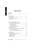
Example 1: Diamond Vipper V770 golden finger is compatible with
2X/4X mode AGP slot. It can be switched between AGP 2X(3.3V) or 4X
(1.5V) mode by adjusting the jumper. The factory default for this card is
2X(3.3V).
The GA-7VAX-A / GA-7VAX1394-A / GA-7VAXP-A / GA-7VAXP-A Ultra
motherboards might not function properly, if you install this card without
switching the jumper to 4X(1.5V) mode in it.
Example 2: Some ATi Rage 128 Pro graphics cards made by "Power
Color", the graphics card manufacturer & some SiS 305 cards, their
golden finger is compatible with 2X(3.3V)/4X(1.5V) mode AGP slot, but
they support 2X(3.3V) only.
The GA-7VAX-A / GA-7VAX1394-A / GA-7VAXP-A / GA-7VAXP-A Ultra
motherboards might not function properly, If you install this card in it.
Note : Although Gigabyte's AG32S(G) graphics card is based on
ATi Rage 128 Pro chip, the design of AG32S(G) is compliance
with AGP 4X(1.5V) specification. Therefore, AG32S (G)will work
fine w
ith VIA
®
KT400A based motherboards.
Before you install PCI cards, please remove the Dual BIOS
label from PCI slots if there is one.
AGP 4X/8X notch