Gigabyte GA-7VT880 User Manual
Gigabyte GA-7VT880 Manual
 |
View all Gigabyte GA-7VT880 manuals
Add to My Manuals
Save this manual to your list of manuals |
Gigabyte GA-7VT880 manual content summary:
- Gigabyte GA-7VT880 | User Manual - Page 1
compatible with 2X(3.3V) / 4X(1.5V) mode AGP slot, but they support 2X(3.3V) only. The GA-7VT880 Pro / GA-7VT880-L / GA-7VT880 (or any AGP 4X/8X only) motherboards might not function properly, If you install this card in it. Note : Although Gigabyte's AG32S(G) graphics card is based on ATi Rage 128 - Gigabyte GA-7VT880 | User Manual - Page 2
The author assumes no responsibility for any errors or omissions that may appear in this document nor does the author make a commitment to update the information contained herein. Third-party brands and names are the property of their respective owners. Please do not remove any labels on motherboard - Gigabyte GA-7VT880 | User Manual - Page 3
Mother Board GA-7VT880 Pro / GA-7VT880-L / GA-7VT880 May 13, 2004 - Gigabyte GA-7VT880 | User Manual - Page 4
Phone/Fax No: (818) 854-9338/ (818) 854-9339 hereby declares that the product Product Name: Motherboard Model Number: GA-7VT880 Pro /GA-7VT880-L /GA-7VT880 Conforms to the following specifications: FCC Part 15, Subpart B, Section 15.107(a) and Section 15.109(a), Class B Digital Device Supplementary - Gigabyte GA-7VT880 | User Manual - Page 5
GA-7VT880 Series AMD Socket A Processor Motherboard USER'S MANUAL AMD Athlon™ / Athlon™ XP / Duron™ Socket A Processor Motherboard Rev. 1002 12ME-7VT880-1002 - Gigabyte GA-7VT880 | User Manual - Page 6
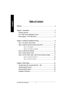
English Table of Content Warning 4 Chapter 1 Introduction 5 Features Summary 5 GA-7VT880 Series Motherboard Layout 7 Block Diagram - GA-7VT880 Series 8 Chapter 2 Hardware Installation Process 9 Step 1: Set System Jumper (SW1 9 Step 2: Install the Central Processing Unit (CPU 10 Step 2-1: - Gigabyte GA-7VT880 | User Manual - Page 7
English Power Management Setup 40 PnP/PCI Configurations 41 PC Health Status 42 MB Intelligent Tweaker (M.I.T 43 Load Fail-Safe Defaults 45 Load Optimized Defaults 45 Set Supervisor/User Password 46 Save & Exit Setup 47 Exit Without Saving 47 Chapter 4 Technical Reference 49 @BIOS™ - Gigabyte GA-7VT880 | User Manual - Page 8
any printed circuit write or parts on the PCB that are near the fixing hole, otherwise it may damage the board or cause board malfunctioning. GA-7VT880 Serie Motherboard - 4 - - Gigabyte GA-7VT880 | User Manual - Page 9
On-Board SATA(Note2) On-Board Peripherals On-Board LAN GA-7VT880 Series: GA-7VT880 Pro / GA-7VT880-L / GA-7VT880 Socket A processor AMD AthlonTM/ AthlonTM XP/ DuronTM (K7) 128K L1 & 512K/256K/64K L2 cache on die 200/266/333/400 MHz FSB Supports 1.4GHz and faster VIA KT880 Memory/AGP Controller (PAC - Gigabyte GA-7VT880 | User Manual - Page 10
- Thermal shutdown function BIOS - Licensed Award BIOS - Supports Q-Flash / Dual BIOS j Additional Features - Supports @BIOS - Supports EasyTune Overclocking - Over Voltage (CPU/AGP/DDR/PCI) CPU, Chipsets, SDRAM, Cards... etc. j Only for GA-7VT880 Pro. GA-7VT880 Serie Motherboard - 6 - - Gigabyte GA-7VT880 | User Manual - Page 11
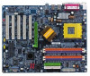
Series Motherboard Layout KB_MS CPU_FAN ATX COMA SOCKET A GA-7VT880 Pro RAM_LED PWR_FANj COMB LPT DDR1 DDR2 DDR3 DDR4 CI SYS_FAN INFO_LINK CLR_CMOS USB LANjk USB AUDIO ATX_12V VIA KT880 SW1 F_AUDIO RLT8110Sj RLT8100Ck CODEC CD_IN - Gigabyte GA-7VT880 | User Manual - Page 12
LINE-IN LINE-OUT VT6306 24 MHz 2 COM Ports 33 MHz PS/2 KB/Mouse 8 USB Ports 3 IEEE1394 ATA33/66/100/133 IDE Channels j Only for GA-7VT880 Pro. k Only for GA-7VT880-L. GA-7VT880 Serie Motherboard - 8 - - Gigabyte GA-7VT880 | User Manual - Page 13
system bus frequency can be switched at 100/133/166/200MHz by adjusting SW1. SW1 ON 100MHz OFF AUTO 100MHz : Fix FSB 200MHz CPU AUTO : Supports FSB 400/333/266 MHz CPU You must set SW1 to "ON" when you used FSB 200MHz CPU. ON SW1 - 9 - Hardware Installation Process - Gigabyte GA-7VT880 | User Manual - Page 14
Before installing the processor, adhere to the following warning: 1. Please make sure the CPU type is supported by the motherboard. 2. If you do not match the CPU socket Pin 1 and CPU cut edge edge on the CPU upper corner. Then insert the CPU into the socket. GA-7VT880 Serie Motherboard - 10 - - Gigabyte GA-7VT880 | User Manual - Page 15
CPU fan power cable is plugged in to the CPU fan connector, this completes the installation. Please refer to CPU cooling fan user's manual for more detail installation procedure. 1. Press down the CPU socket lever and finish CPU installation. 2. Use qualified fan approved by AMD. 3. Fasten the - Gigabyte GA-7VT880 | User Manual - Page 16
the DIMM memory module can only fit in one direction. 2. Insert the DIMM memory module vertically into the DIMM socket. Then push it down. GA-7VT880 Serie Motherboard 3. Close the plastic clip at both edges of the DIMM sockets to lock the DIMM module. Reverse the installation steps when you wish - Gigabyte GA-7VT880 | User Manual - Page 17
GA-7VT880 Pro / GA-7VT880-L / GA-7VT880 support Dual Channel Technology. When Dual Channel Technology is activated, the bandwidth of memory bus will be double the original one, with the fastest speed at 6.4GB/s(DDR400) . GA-7VT880 Pro / GA-7VT880-L / GA-7VT880 card's instruction document before - Gigabyte GA-7VT880 | User Manual - Page 18
(COMA / COMB) This connector supports 2 standard COM ports Parallel Port (25 pin Female) and 1 Parallel port. Devices like printer can be connected to Parallel port; mouse and modem etc. can be connected to Serial ports. COMA COMB Serial Port (9 pin Male) GA-7VT880 Serie Motherboard - 14 - - Gigabyte GA-7VT880 | User Manual - Page 19
etc. Have a standard USB interface. Also make sure your OS supports USB controller. If your OS does not support USB controller, please contact OS vendor for possible patch or driver please refer to page 57. j Only for GA-7VT880 Pro. k Only for GA-7VT880-L. - 15 - Hardware Installation Process - Gigabyte GA-7VT880 | User Manual - Page 20
14) SUR_CEN 15) SPDIF_IO 16) CD_IN 17) AUX_IN 18) F_USB1 / F_USB2 19) F1_1394 / F2_1394 20) IR 21) GAME 22) INFO_LINK 23) CLR_CMOS 24) C I j Only for GA-7VT880 Pro. GA-7VT880 Serie Motherboard - 16 - - Gigabyte GA-7VT880 | User Manual - Page 21
English 1) ATX_12V (+12V Power Connector) This connector (ATX_12V) supplies the CPU operation voltage (Vcore). If this "ATX_12V connector" is not connected, system cannot boot. 13 24 Pin No. 1 2 3 4 Definition GND GND +12V +12V 2) ATX (ATX Power) AC power cord should only be connected to your - Gigabyte GA-7VT880 | User Manual - Page 22
connector supports Max. current up to 600 mA. Pin No. Definition 1 1 GND 2 +12V 3 Sense 4) SYS_FAN (System Fan Connector) This connector allows you to link with the cooling fan on the system case to lower the system temperature. Pin No. Definition 1 GND 2 +12V 1 3 Sense GA-7VT880 - Gigabyte GA-7VT880 | User Manual - Page 23
FDD (Floppy Connector) Please connect the floppy drive ribbon cables to FDD. It supports 360K, 1.2M, 720K, 1.44M and 2.88M bytes floppy disk types. The red stripe of the ribbon cable must be the same side with the Pin1. 34 33 j Only for GA-7VT880 Pro. 2 1 - 19 - Hardware Installation Process - Gigabyte GA-7VT880 | User Manual - Page 24
function, please use it in unity with BIOS and install the correct driver to have proper operation. For details, please refer to the SATA RAID manual. Pin No. Definition 1 GND 2 TXP 7 1 3 TXN 4 GND 5 RXN 6 RXP 7 GND GA-7VT880 Serie Motherboard - 20 - - Gigabyte GA-7VT880 | User Manual - Page 25
English 9) F_PANEL (2 x 10 pins Connector) Please connect the power LED, PC speaker, reset switch and power switch etc. of your chassis front panel to the F_PANEL connector according to the pin assignment above. Speaker Connector Soft Power Connector Message LED/ Power/ Sleep LED 20 19 SPEAK- - Gigabyte GA-7VT880 | User Manual - Page 26
or equivalent type recommended by the manufacturer. Dispose of used batteries according to the manufacturer's instructions. If you want to erase CMOS... 1. Turn OFF the computer and unplug the power another color. Pin No. Definition 1 MPD+ 1 2 MPD- 3 MPD- GA-7VT880 Serie Motherboard - 22 - - Gigabyte GA-7VT880 | User Manual - Page 27
pin assigment on the cable is the same as the pin assigment on the MB header. To find out if the chassis you are buying support front audio connector, please contact your dealer. Please note, you can have the alternative of using front audio connector or of using rear audio connector - Gigabyte GA-7VT880 | User Manual - Page 28
or even damage it. For optional SPDIF_IO cable, please contact your local dealer. 26 15 Pin No. 1 2 3 4 5 6 Definition VCC No Pin SPDIF_O SPDIFI GND GND GA-7VT880 Serie Motherboard - 24 - - Gigabyte GA-7VT880 | User Manual - Page 29
English 16) CD_IN (CD In Connector) Connect CD-ROM or DVD-ROM audio out to the connector. 1 Pin No. Definition 1 CD-L 2 GND 3 GND 4 CD-R 17) AUX_IN (AUX In Connector) Connect other device (such as PCI TV Tunner audio out) to the connector. 1 Pin No. Definition 1 AUX-L 2 GND 3 GND - Gigabyte GA-7VT880 | User Manual - Page 30
GND TPB0+ TPB0Power Power TPA1+ TPA1GND No Pin TPB1+ TPB1- F1_1394 2 10 1 9 Pin No. 1 2 3 4 5 6 7 8 9 10 Definition TPA2+ TPA2GND GND TPB2+ TPB2No Pin Power Power GND GA-7VT880 Serie Motherboard - 26 - - Gigabyte GA-7VT880 | User Manual - Page 31
your local dealer. 1 5 Pin No. 1 2 3 4 5 Definition VCC(+5V) No Pin IR Data Input GND IR Data Output 21) GAME (Game Connector) This connector supports joystick, MIDI keyboard and other relate audio devices. Check the pin assignment while you connect the game cables. Please contact your nearest - Gigabyte GA-7VT880 | User Manual - Page 32
this jumper. Default doesn't include the "Shunter"to prevent from improper use this jumper. To clear CMOS, temporarily short 1-2 pin. 1 Open: Normal 1 1-2 close: Clear CMOS GA-7VT880 Serie Motherboard - 28 - - Gigabyte GA-7VT880 | User Manual - Page 33
English 24) CI (CASE OPEN) This 2 pin connector allows your system to enable or disable the "case open" item in BIOS if the system case begin remove. Pin No. Definition 1 1 Signal 2 GND - 29 - Hardware Installation Process - Gigabyte GA-7VT880 | User Manual - Page 34
English GA-7VT880 Serie Motherboard - 30 - - Gigabyte GA-7VT880 | User Manual - Page 35
English Chapter 3 BIOS Setup BIOS Setup is an overview of the BIOS Setup Program. The program that allows users to modify the basic system configuration. This type of information is stored in battery-backed CMOS RAM so that it retains the Setup information when the power is turned off. ENTERING - Gigabyte GA-7VT880 | User Manual - Page 36
setup page includes all the items of Green function features. l PnP/PCI Configurations This setup page includes all the configurations of PCI & PnP ISA resources. GA-7VT880 Serise Motherboard - 32 - - Gigabyte GA-7VT880 | User Manual - Page 37
English l PC Health Status This setup page is the System auto detect Temperature, voltage, fan, speed. l MB Intelligent Tweaker (M.I.T) This setup page is control CPU's clock and frequency ratio. l Load Fail-Safe Defaults Fail-Safe Defaults indicates the value of the system parameters which the - Gigabyte GA-7VT880 | User Manual - Page 38
F that has been installed in the computer. There are two types: auto type, and manual type. Manual type is user-definable; Auto type which will automatically detect HDD type. Note that the specifications has not been installed, select NONE and press . GA-7VT880 Serise Motherboard - 34 - - Gigabyte GA-7VT880 | User Manual - Page 39
capacity 1.44M, 3.5" 3.5 inch double-sided drive; 1.44M byte capacity. 2.88M, 3.5" 3.5 inch double-sided drive; 2.88M byte capacity. Floppy 3 Mode Support (for Japan Area) Disabled Normal Floppy Drive. (Default value) Drive A Drive A is 3 mode Floppy Drive. Drive B Drive B is 3 mode Floppy - Gigabyte GA-7VT880 | User Manual - Page 40
prompt. Setup The system will boot, but access to Setup will be denied if the correct password is not entered at the prompt. (Default value) GA-7VT880 Serise Motherboard - 36 - - Gigabyte GA-7VT880 | User Manual - Page 41
Disabled Enable onboard 2nd channel IDE port. (Default value) Disable onboard 2nd channel IDE port. OnChip Serial ATA Enabled Disabled Enable VT8237 Serial ATA supported. (Default value) Disable VT8237 Serial ATA supported. j Only for GA-7VT880 Pro. k Only for GA-7VT880-L. - 37 - BIOS Setup - Gigabyte GA-7VT880 | User Manual - Page 42
Support Enabled Enable USB keyboard support. Disabled Disable USB keyboard support. (Default value) USB Mouse Support Enabled Enable USB mouse support. Disabled Disable USB mouse support Serial port 2. j Only for GA-7VT880 Pro. k Only for GA-7VT880-L. GA-7VT880 Serise Motherboard - 38 - - Gigabyte GA-7VT880 | User Manual - Page 43
English UART Mode Select This item allows you to determine which infrared(IR) function of onboard I/O chip. Normal Set onboard I/O chip using as standard serial port. (Default value) IrDA Set onboard I/O chip UART to IrDA Mode. ASKIR Set onboard I/O chip UART to ASKIR Mode. UR2 Duplex Mode - Gigabyte GA-7VT880 | User Manual - Page 44
can press the key to power on your system. Mouse Power On Disabled Enabled Disabled this function. (Default value) Power on system by mouse event. GA-7VT880 Serise Motherboard - 40 - - Gigabyte GA-7VT880 | User Manual - Page 45
English PME Event Wake Up Disabled Disable this function. Enabled Enable PME as wake up event. (Default value) ModemRingOn/WakeOnLAN (When AC Back Function set to [Soft-Off]) An incoming call via modem awakes the system from its soft-off mode. When set at Enabled, an input signal comes from - Gigabyte GA-7VT880 | User Manual - Page 46
value) Enabled Fan warning function enable. SYSTEM FAN Fail Warning Disabled Fan warning function disable. (Default value) Enabled Fan warning function enable. F1: General Help GA-7VT880 Serise Motherboard - 42 - - Gigabyte GA-7VT880 | User Manual - Page 47
BIOS will automatically setup the DRAM Timing by DRAM SPD data. (Default value) This item allows user to set DRAM Timing Manually. DRAM CAS Latency 1.5/2/2.5/3 Set DRAM CAS Latency time to 1.5/2/2.5/3(Default value:2.5). Bank Interleave This feature allows user to select the DRAM access method - Gigabyte GA-7VT880 | User Manual - Page 48
CPU voltage may get stable for Over_Clock. But it may damage to CPU when enable this feature. Supports adjustable CPU Vcore from 1.100V to 2.05V by 0.005V step. (Default value: Normal) Normal 2V Increase DDR voltage +0.2V. +0.3V Increase DDR voltage +0.3V. GA-7VT880 Serise Motherboard - 44 - - Gigabyte GA-7VT880 | User Manual - Page 49
English Load Fail-Safe Defaults CMOS Setup Utility-Copyright (C) 1984-2004 Award Software } Standard CMOS Features Load Fail-Safe Defaults } Advanced BIOS Features Load Optimized Defaults } Integrated Peripherals Set Supervisor Password } Power Management Setup Set User Password } PnP/PCI - Gigabyte GA-7VT880 | User Manual - Page 50
Setup Menu. If you select "Setup" at "Password Check" in Advance BIOS Features Menu, you will be prompted only when you try to enter Setup. GA-7VT880 Serise Motherboard - 46 - - Gigabyte GA-7VT880 | User Manual - Page 51
English Save & Exit Setup CMOS Setup Utility-Copyright (C) 1984-2004 Award Software } Standard CMOS Features Load Fail-Safe Defaults } Advanced BIOS Features Load Optimized Defaults } Integrated Peripherals Set Supervisor Password } Power Management Setup Set User Password } PnP/PCI - Gigabyte GA-7VT880 | User Manual - Page 52
English GA-7VT880 Serise Motherboard - 48 - - Gigabyte GA-7VT880 | User Manual - Page 53
could not just do something right to save your time and effort and save you from the lousy BIOS updating work? Here it comes! Now Gigabyte announces @BIOS -- the first Windows BIOS live update utility. This is a smart BIOS update software. It could help you to download the BIOS from internetand - Gigabyte GA-7VT880 | User Manual - Page 54
BIOS from Floppy Update Backup BIOS from Floppy Save Main BIOS to Floppy PgDn/PgUp: Modify Save Backup BIOS to Floppy hi: Move ESC: Reset GA-7VT880 Series Motherboard - 50 - 512K 512K F10: Power Off - Gigabyte GA-7VT880 | User Manual - Page 55
Halt On Error set to Enable, the PC will show messages on the boot screen, and the system will pause and wait for the user's instruction. If Auto Recovery :Disable, it will show If Auto Recovery :Enable, it will show - Gigabyte GA-7VT880 | User Manual - Page 56
have accomplished the saving. CONTROL KEYS Make changes Move to previous item Move to next item Run Reset Power Off GA-7VT880 Series Motherboard - 52 - - Gigabyte GA-7VT880 | User Manual - Page 57
GIGABYTE, is available on this motherboard. Future GIGABYTE motherboards will also incorporate this innovation. What's DualBIOS™ ? On GIGABYTE next system boot. Almost automatically and with virtually zero down time! Whether the problem is a failure in flashing your BIOS or a virus or a catastrophic - Gigabyte GA-7VT880 | User Manual - Page 58
from the main system BIOS. The DualBIOS™ utility may be entered to manually change the boot sequence to boot from the backup BIOS. 2. During Most workstation/servers require constant operation to guarantee services have not been interrupted. In this situation, the GA-7VT880 Series Motherboard - 54 - - Gigabyte GA-7VT880 | User Manual - Page 59
DOS boot disk, we recommend that you used Gigabyte @BIOS™ program to flash BIOS. Press here. 1. Click "@BIOS" item. 2. Click Start/ Programs/ GIGABYTE/ @BIOS. (1) (2) 3.Click "P". Click here as: 7VT880PRO.F2). e. Complete update process following the instruction. - 55 - Technical Reference - Gigabyte GA-7VT880 | User Manual - Page 60
check out which kind of motherboard and which brand of Flash ROM are supported. Note: a. In method I, if it shows two or more Gigabyte's web site for downloading and updating it according to method II. d. Please note that any interruption during updating will cause system unbooted. GA-7VT880 - Gigabyte GA-7VT880 | User Manual - Page 61
English R2-e/4v-is/6io-CnhHainsntoerlyAudio Function Introuction The installation of windows 98SE/2K/ME/XP is very simple. Please follow next step to install the function! Stereo Speakers Connection and Settings: We recommend that you use the speaker with amplifier to acqiire the best sound effect - Gigabyte GA-7VT880 | User Manual - Page 62
"OK". When the "Environment settings" is "None", the sound would be performed as stereo mode (2 channels output). Please select the other settings for 4 channels output. GA-7VT880 Series Motherboard - 58 - - Gigabyte GA-7VT880 | User Manual - Page 63
English Basic 6 Channel Analog Audio Output Mode Use the back audio panel to connect the audio output without any additional module. STEP 1 : Connect the front channels to "Line Out",the rear channels to "Line In", and the Center/Subwoofer channels to "MIC In". MIC In Line Out STEP 2 : After - Gigabyte GA-7VT880 | User Manual - Page 64
, Line In and MIC at the same time. "SURROUND-KIT" is included in the GIGABYTE unique "Audio Combo Kit" as picture. STEP 1 : Insert the "SURROUND-KIT" in the back of the case , and fix it with the screw. STEP 2 : Connect the "SURROUND-KIT" to SUR_CEN on the M/B. GA-7VT880 Series Motherboard - 60 - - Gigabyte GA-7VT880 | User Manual - Page 65
English STEP 3 : Connect the front channels to back audio panel's "Line Out", the rear channels to SURROUND-KIT's REAR R/L, and the Center/Subwoofer channels to SURROUND-KIT's SUB CENTER. STEP 4 : Click the audio icon "Sound Effect" from the windows tray at the bottom of the screen. STEP 5 : Select - Gigabyte GA-7VT880 | User Manual - Page 66
output device to the rear bracket of PC, and fix it with screw. 2. Connect SPDIF device to the motherboard. 3. Connect SPDIF to the SPDIF decoder. GA-7VT880 Series Motherboard - 62 - - Gigabyte GA-7VT880 | User Manual - Page 67
connectors error-detection function. Install Microsoft DirectX8.1 or later version before to enable Jack-Sensing support for Windows 98/ 98SE/2000/ME. Jack-Sensing includes 2 parts: AUTO and MANUAL. Following is an example for 2 channels (Windows XP): Introduction of audio connectors You may connect - Gigabyte GA-7VT880 | User Manual - Page 68
English If you set wrong with the connectors, the warning message will come out as right picture. Manual setting: If the device picture shows different from what you set, please press "Manual Selection" to set. GA-7VT880 Series Motherboard - 64 - - Gigabyte GA-7VT880 | User Manual - Page 69
Line-in or Line-out jack, the device will work perfectly after UAJ is activated. Install Microsoft DirectX8.1 or later version before to enable UAJ support for Windows 98/98SE/ 2000/ME. PS. If UAJ couldn't work as expected, please disable this function by pressing button "UAJ information". And then - Gigabyte GA-7VT880 | User Manual - Page 70
volume lever in the "Volume Control" menu to adjust the volume because AUX IN and Line-In functions are controlled by the same audio signals. GA-7VT880 Series Motherboard - 66 - - Gigabyte GA-7VT880 | User Manual - Page 71
installation of only one OS 4. Must be used with an IDE hard disk supporting HPA 5. The first partition must be set as the boot partition. When the from CD: Boot from CD: Xpress Recovery V1.0 (C) Copy Right 2003. GIGABYTE Technology CO. , Ltd. 1. Execute Backup Utility 2. Execute Restore Utility - Gigabyte GA-7VT880 | User Manual - Page 72
/16/2002-I845GE-6A69YG01C-00 F9 For Xpress Recovery Xpress Recovery V1.0 (C) Copy Right 2003. GIGABYTE Technology CO. , Ltd. 1. Execute Backup Utility 2. Execute Restore Utility 3. Remove Backup Image required driver and software installations are complete. GA-7VT880 Series Motherboard - 68 - - Gigabyte GA-7VT880 | User Manual - Page 73
Esc to Exit The backup utility will automatically scan your system and back up data as a backup image in your hard drive. Not all systems support access to Xpress Recovery by pressing the F9 key during computer power on. If this is the case, please use the boot from CD-ROM - Gigabyte GA-7VT880 | User Manual - Page 74
English GA-7VT880 Series Motherboard - 70 - - Gigabyte GA-7VT880 | User Manual - Page 75
number of drive members times the capacity of the smallest member. The striping block size can be set from 4KB to 64KB. RAID 0 does not support fault tolerance. RAID 1 (Mirroring) RAID 1 writes duplicate data onto a pair of drives and reads both sets of data in parallel. If one of the mirrored - Gigabyte GA-7VT880 | User Manual - Page 76
and 5 is provided. (For more detailed setup information, please visit our website at http:\\www.gigabyte.com.tw) Enter BIOS Configuration Utility When the system powers on, the following information will appear on SATA SATA Size(GB) 74.53 111.79 Status Hdd Hdd GA-7VT880 Series Motherboard - 72 - - Gigabyte GA-7VT880 | User Manual - Page 77
English Create Disk Array 1. Use the arrow keys to navigate the main menu. Use the up and down arrow keys to select the Create Array command and press to call out the list of creation steps. VIA Technologies,Inc. VIA VT8237 Serial ATA BIOS Setting Utility V1.20 u Auto Setup For Data - Gigabyte GA-7VT880 | User Manual - Page 78
Y to finish the creation, or press N to cancel the creation. 6. Important note: All existing content in the hard drive will be destroyed after array creation. GA-7VT880 Series Motherboard - 74 - - Gigabyte GA-7VT880 | User Manual - Page 79
English Delete Disk Array A RAID can be deleted after it has been created. To delete a RAID, use the following steps: 1. Select Delete Array in the main menu and press . The channel column will be activated. 2. Select the member of an array that is to be deleted and press . A warning - Gigabyte GA-7VT880 | User Manual - Page 80
Status h, i : Move to next item Enter : Confirm the selection ESC : Exit Array Name ARRAY0 Array Mode Stripe Block Size(GB) Size(GB) 64K 149.06 GA-7VT880 Series Motherboard - 76 - - Gigabyte GA-7VT880 | User Manual - Page 81
in serial ATA controller, press F6 as Win2000 or XP boots up, then supply serial ATA controller driver by this floppy disk. Follow on-screen instructions to complete installation. (Each time you add a new hard drive to a RAID array, the RAID driver will have to be installed under Windows once for - Gigabyte GA-7VT880 | User Manual - Page 82
English GA-7VT880 Series Motherboard - 78 - - Gigabyte GA-7VT880 | User Manual - Page 83
CD-ROM drive, the driver CD-title will auto start and show the installation guide. If not, please double click the CD-ROM device icon in "My be installed for the system. Click each item to install the driver manually or switch to the to install the drivers automatically. The "Xpress Install - Gigabyte GA-7VT880 | User Manual - Page 84
install Windows Service Pack, it will show a question mark "?" in "Universal Serial Bus controller" under "Device Manager". Please remove the question mark and restart the system (System will auto-detect the right USB2.0 driver). j Only for GA-7VT880 Pro. k Only for GA-7VT880-L. GA-7VT880 Series - Gigabyte GA-7VT880 | User Manual - Page 85
the system n Face-Wizard New utility for adding BIOS logo n @BIOS Gigabyte windows flash BIOS utility n Acrobat e-Book Useful utility from Adobe n AcrobatReader Popular DirectX 9 to enable 3D hardware acceleration that support for operating system to achieve better 3D performence. - 81 - Appendix - Gigabyte GA-7VT880 | User Manual - Page 86
English SOFTWARE INFORMATION This page list the contects of softwares and drivers in this CD title. HARDWARE INFORMATION This page lists all device you have for this motherboard. CONTACT US Contact us via the information in this page all over the world. GA-7VT880 Series Motherboard - 82 - - Gigabyte GA-7VT880 | User Manual - Page 87
steps in the installation process. Therefore, we suggest that you refer to the installation steps in the RAID manual at our website. (Please download it at http://tw.giga-byte.com/support/user_pdf/raid_manual.pdf) Question 5: How do I clear CMOS? Answer: If your board has a Clear CMOS jumper, please - Gigabyte GA-7VT880 | User Manual - Page 88
system instability still remains, please clear CMOS to solve the problem. Question 7: Why do I still get a weak sound after : Gigabyte motherboards will auto-detect the external VGA card after it is plugged in, so you don't need to change any setting manually to GA-7VT880 Series Motherboard - 84 - - Gigabyte GA-7VT880 | User Manual - Page 89
English Question 11: How to set in the BIOS in order to bootup from SATA HDDs by either RAID or ATA mode? Answer: Please set in the BIOS as follow: 1. Advanced BIOS features--> SATA/RAID/SCSI boot order: "SATA" 2. Advanced BIOS features--> First boot device: "SCSI" 3. Integrated Peripherals--> - Gigabyte GA-7VT880 | User Manual - Page 90
If you encounter any trouble during boot up, please follow the troubleshooting procedures. START Turn off the power and unplug the AC power cable, then remove all of the been excluded. Insert the VGA card. Then plug in ATX power cable and turn on the system. A GA-7VT880 Series Motherboard - 86 - - Gigabyte GA-7VT880 | User Manual - Page 91
If the above procedure unable to solve your problem, please contact with your local retailer or national distributor for help. Or, you could submit your question to the service mail via Gigabyte website technical support zone (http://www.gigabyte.com.tw). The appropriate response will be provided - Gigabyte GA-7VT880 | User Manual - Page 92
& English Technical Support/RMA Sheet Customer/Country: Contact Person: Company: E-mail Add. : Model name/Lot Number: BIOS version: AMR / CNR Keyboard Mouse Power supply Other Device Phone No.: PCB revision: Driver/Utility: Problem Description: & GA-7VT880 Series Motherboard - 88 - - Gigabyte GA-7VT880 | User Manual - Page 93
English Appendix E: Acronyms Acronyms Meaning ACPI Advanced Configuration and Power Interface APM Advanced Power Management AGP Accelerated Graphics Port AMR Audio Modem Riser ACR Advanced Communications Riser BIOS Basic Input / Output System CPU Central Processing Unit CMOS - Gigabyte GA-7VT880 | User Manual - Page 94
Power-On Self Test Peripheral Component Interconnect Rambus in-line Memory Module Special Circumstance Instructions Single Edge Contact Cartridge Static Random Access Memory Symmetric Multi-Processing System Management Interrupt Universal Serial Bus Voltage ID GA-7VT880 Series Motherboard - 90 - - Gigabyte GA-7VT880 | User Manual - Page 95
- 91 - Appendix English - Gigabyte GA-7VT880 | User Manual - Page 96
854-9338 Fax: 1 (626) 854-9339 Tech. Support: http://www.giga-byte.com/TechSupport/ServiceCenter.htm Non-Tech. Support (Sales/Marketing issues): http://ggts.gigabyte.com.tw/nontech.asp Website: http://www.giga-byte Xian Tel: 86-29-5531943 Fax: 86-29-5539821 GA-7VT880 Series Motherboard - 92 -
-
 1
1 -
 2
2 -
 3
3 -
 4
4 -
 5
5 -
 6
6 -
 7
7 -
8
-
9
-
10
-
11
-
12
-
13
-
14
-
15
-
16
-
17
-
18
-
19
-
20
-
21
-
22
-
23
-
24
-
25
-
26
-
27
-
28
-
29
-
30
-
31
-
32
-
33
-
34
-
35
-
36
-
37
-
38
-
39
-
40
-
41
-
42
-
43
-
44
-
45
-
46
-
47
-
48
-
49
-
50
-
51
-
52
-
53
-
54
-
55
-
56
-
57
-
58
-
59
-
60
-
61
-
62
-
63
-
64
-
65
-
66
-
67
-
68
-
69
-
70
-
71
-
72
-
73
-
74
-
75
-
76
-
77
-
78
-
79
-
80
-
81
-
82
-
83
-
84
-
85
-
86
-
87
-
88
-
89
-
90
-
91
-
92
-
93
-
94
-
95
-
96
 |
 |
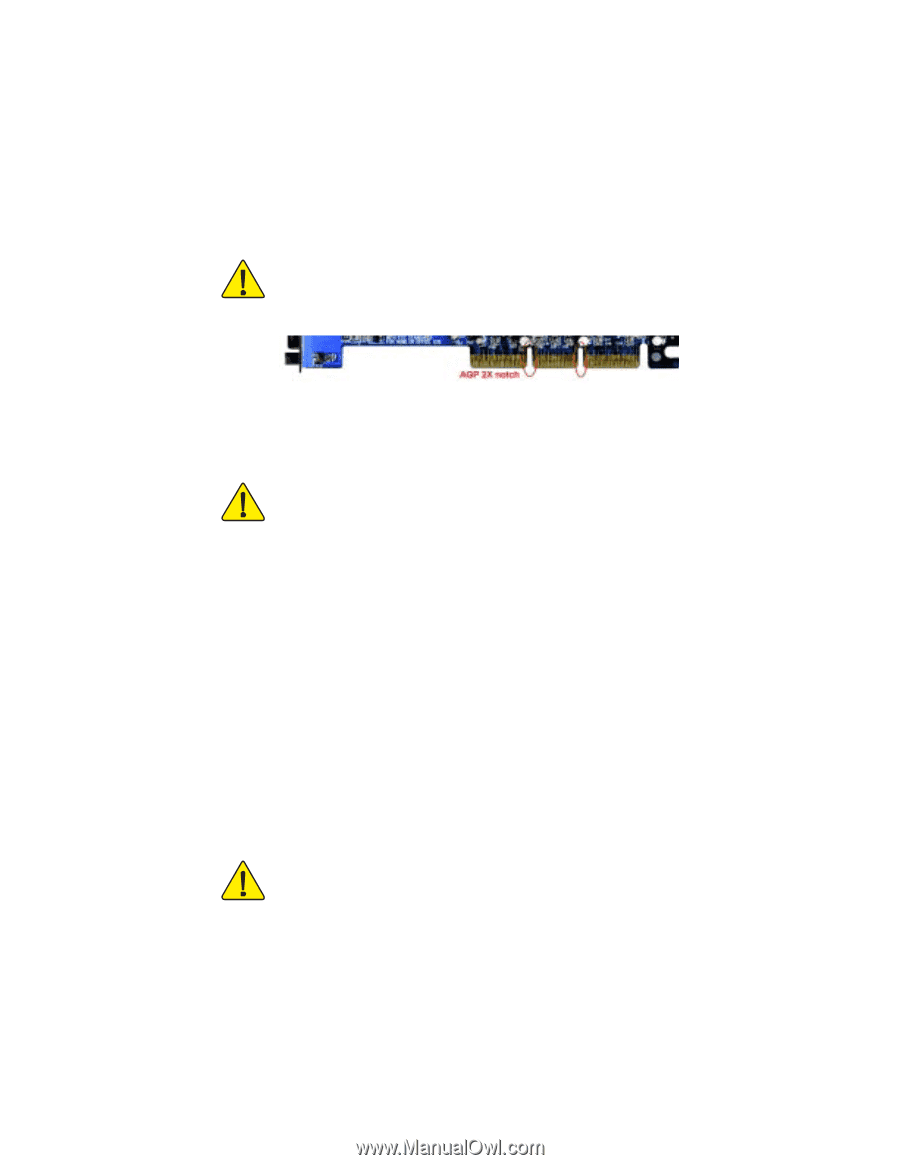
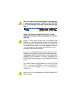
When you installing AGP card, please make sure the following notice
is fully understood and practiced.
If your AGP card has "AGP 4X/8X
(1.5V) notch"(show below), please make sure your AGP card is AGP
4X/8X.
Caution: AGP 2X card is not supported by VIA KT880. You might
experience system unable to boot up normally. Please insert an AGP
4X/8X card.
Example 1: Diamond Vipper V770 golden finger is compatible with 2X/4X
mode AGP slot. It can be switched between AGP 2X(3.3V) or 4X(1.5V) mode
by adjusting the jumper. The factory default for this card is 2X(3.3V). The
GA-7VT880 Pro / GA-7VT880-L / GA-7VT880 (or any AGP 4X/8X only)
motherboards might not function properly, if you install this card without
switching the jumper to 4X(1.5V) mode in it.
Example 2: Some ATi Rage 128 Pro graphics cards made by "Power Color",
the graphics card manufacturer & some SiS 305 cards, their golden finger is
compatible with 2X(3.3V) / 4X(1.5V) mode AGP slot, but they support
2X(3.3V) only. The GA-7VT880 Pro / GA-7VT880-L / GA-7VT880 (or any
AGP 4X/8X only) motherboards might not function properly, If you install this
card in it.
Note : Although Gigabyte's AG32S(G) graphics card is based on ATi Rage
128 Pro chip, the design of AG32S(G) is compliance with AGP 4X(1.5V)
specification. Therefore, AG32S(G) will work fine with VIA KT880 based
motherboards.
Before you install PCI cards, please remove the Dual BIOS label from PCI
slots if there is one.
AGP 4X/8X notch