Gigabyte GA-8AENXP-D Manual
Gigabyte GA-8AENXP-D Manual
 |
View all Gigabyte GA-8AENXP-D manuals
Add to My Manuals
Save this manual to your list of manuals |
Gigabyte GA-8AENXP-D manual content summary:
- Gigabyte GA-8AENXP-D | Manual - Page 1
GA-8AENXP-D Intel® Pentium® 4 LGA775 Processor Motherboard User's Manual Rev. 1004 12ME-8AENXPD-1004 - Gigabyte GA-8AENXP-D | Manual - Page 2
Motherboard GA-8AENXP-D Nov. 10, 2004 Motherboard GA-8AENXP-D Nov. 10, 2004 - Gigabyte GA-8AENXP-D | Manual - Page 3
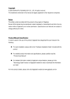
product information and specifications, please carefully read the "Product User Manual". „ For detailed information related to Gigabyte's unique features, please go to the "Technology Guide" section on Gigabyte's website to read or download the information you need. For more product details, please - Gigabyte GA-8AENXP-D | Manual - Page 4
Table of Contents GA-8AENXP-D Motherboard Layout 6 Block Diagram ...7 Chapter 1 Hardware Installation 9 1-1 Considerations Prior to Installation 9 1-2 Feature Summary 10 1-3 Installation of the CPU and Heatsink 12 1-3-1 Installation of the CPU 12 1-3-2 Installation of the Heatsink 13 1-4 - Gigabyte GA-8AENXP-D | Manual - Page 5
55 4-1 Unique Software Utilities 55 4-1-1 EasyTune 5 Introduction 56 4-1-2 Xpress Recovery Introduction 57 4-1-3 Flash BIOS Method Introduction 60 4-1-4 Serial ATA BIOS Setting Utility Introduction 71 4-1-5 2- / 4- / 6- / 8- Channel Audio Function Introduction 78 4-2 Troubleshooting 83 - 5 - - Gigabyte GA-8AENXP-D | Manual - Page 6
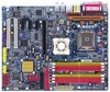
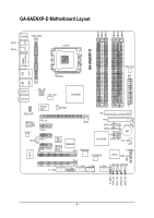
GA-8AENXP-D Motherboard Layout KB_MS VRM_CONN SPDIF_O SPDIF_I LGA775 GA-8AENXP-D COMA LPT LAN2 LAN1 PWR_FAN ATX USB USB AUDIO1 AUDIO2 ATX_12V CPU_FAN Intel 925XE Marvell 8001 NB_FAN AZALIA_FP IDE Broadcom 5751/5789 CODEC PCIE_16 PCIE_1 CD_IN PCIE_2 PCIE_3 IR Main BIOS Backup BIOS - Gigabyte GA-8AENXP-D | Manual - Page 7
DIMM Intel 925XE MCH Intel ICH6R Dual Channel Memory MCHCLK (266/200/133MHz) 66MHz 33MHz 14.318MHz 48MHz Dual BIOS 4 Serial ATA SiI3114 4 Serial ATA ATA33/66/100 IDE Channels Floppy RJ45 CODEC IT 8712 LPT Port COM Port 2 PCI PCICLK (33MHz) 8 USB Ports 3 USB Ports 24MHz PS/2 KB/Mouse - Gigabyte GA-8AENXP-D | Manual - Page 8
- 8 - - Gigabyte GA-8AENXP-D | Manual - Page 9
instructions below: 1. Please turn off the computer and unplug its power cord. 2. When handling the motherboard , avoid touching any metal leads or connectors. 3. It is best to wear an electrostatic discharge (ESD) cuff when handling electronic components (CPU motherboard problem manual - Gigabyte GA-8AENXP-D | Manual - Page 10
memory during system startup. (Note 2) To use a DDRII 711 memory module on the motherboard, you must install a 1066MHz FSB processor and overclock in BIOS. To use a DDRII 600 memory module on the motherboard, you must install an 800MHz FSB processor and overclock in BIOS. GA-8AENXP-D Motherboard - Gigabyte GA-8AENXP-D | Manual - Page 11
a maximum of 4 SATA connections BIOS - supported on the Win 2000/XP/NT/98/Me operating systems Š Use of licensed AWARD BIOS Š Supports Dual BIOS/Q-Flash/Multilanguage BIOS Additional Features Š Supports U-Plus DPS Š Supports @BIOS Overclocking Š Supports EasyTune 5 Š Over Voltage via BIOS (CPU - Gigabyte GA-8AENXP-D | Manual - Page 12
to your hardware specifications including the CPU, graphics card, memory, hard drive, etc. HT functionality socket in a straight and downwards motion. Avoid twisting or bending motions that might cause damage to the CPU during installation.) GA-8AENXP-D Motherboard - 12 - Fig. 4 Once the CPU - Gigabyte GA-8AENXP-D | Manual - Page 13
the CPU and make sure the push pins aim to the pin hole on the motherboard. Pressing down the push pins diagonally. Fig. 4 Please make sure the Male and Female push pin are joined closely. (for detailed installation instructions, please refer to the heatsink installation section of the user manual - Gigabyte GA-8AENXP-D | Manual - Page 14
the direction. The motherboard supports DDR II memory modules, whereby BIOS will automatically detect memory capacity and specifications. Memory modules are designed so that they can be inserted only in one direction. The memory capacity used can differ with each slot. GA-8AENXP-D Motherboard - 14 - Gigabyte GA-8AENXP-D | Manual - Page 15
wish to remove the DIMM module. Dual Channel DDR II GA-8AENXP-D supports the Dual Channel Technology. After operating the Dual Channel Technology, the bandwidth of Memory Bus will double. GA-8AENXP-D includes 6 DIMM sockets, and each Channel has three DIMM sockets as following: Channel A : DDR II - Gigabyte GA-8AENXP-D | Manual - Page 16
outlined below: 1. Read the related expansion card's instruction document before install the expansion card into the computer on the computer, if necessary, setup BIOS utility of expansion card from BIOS. 8. Install related driver from the operating system. Installing GA-8AENXP-D Motherboard - 16 - - Gigabyte GA-8AENXP-D | Manual - Page 17
make sure your device(s) such as USB keyboard, mouse, scanner, zip, speaker...etc. have a standard USB interface. Also make sure your OS supports USB controller. If your OS does not support USB controller, please contact OS vendor for possible patch or driver upgrade. For more information please - Gigabyte GA-8AENXP-D | Manual - Page 18
Out Connect the side surround speakers to this connector. You can use audio software to configure 2-/4-/6-/8-channel audio functioning. 1-8 Connectors Introduction 13 9 5 2 6 13 8 /SATA2_SB/SATA3_SB 19) CI 10) SATA0_SII/SATA1_SII/SATA2_SII/SATA3_SII 20) BAT GA-8AENXP-D Motherboard - 18 - - Gigabyte GA-8AENXP-D | Manual - Page 19
all components and devices are properly installed. Align the power connector with its proper location on the motherboard and connect tightly. The ATX_12V power connector mainly supplies power to the CPU. If the ATX_12V power connector is not connected, the system will not start. Caution! Please use - Gigabyte GA-8AENXP-D | Manual - Page 20
cooler to prevent system overheating and failure. Caution! Please remember to connect the power to the CPU fan to prevent CPU overheating and failure. 1 CPU_FAN Pin No. 1 2 3 4 1 SYS_FAN / PWR_FAN black cable is GND) 1 Pin No. Definition 1 +12V 2 GND GA-8AENXP-D Motherboard - 20 - - Gigabyte GA-8AENXP-D | Manual - Page 21
cable while the other end of the cable connects to the FDD drive. The types of FDD drives supported are: 360KB, 720KB, 1.2MB, 1.44MB and 2.88MB. Please connect the red power connector wire to , please refer to the instructions located on the IDE device). 2 40 1 39 - 21 - Hardware Installation - Gigabyte GA-8AENXP-D | Manual - Page 22
) Serial ATA can provide 150MB/s transfer rate. Please refer to the BIOS setting for the Serial ATA and install the proper driver in order to work properly. 1 7 SATA_SB (Controlled by ICH6R) enters suspend mode. Pin No. Definition 1 MPD+ 2 MPD- 1 3 MPD- GA-8AENXP-D Motherboard - 22 - - Gigabyte GA-8AENXP-D | Manual - Page 23
English 12) F_PANEL (Front Panel Jumper) Please connect the power LED, PC peaker, reset switch and power switch etc of your chassis front panel to the F_PANEL connector according to the pin assignment below. Speaker Connector Power Switch Message LED/ Power/ Sleep LED SPEAK- 20 19 SPEAK+ PWPW+ - Gigabyte GA-8AENXP-D | Manual - Page 24
for this connector. To enable AC'97 Audio, from BIOS settings, set Front Panel Type under Integrated Peripherals to AC97. 14) CD_IN (CD In Connector) Connect CD-ROM or DVD-ROM audio out to the connector. 1 Pin No. Definition 1 CD-L 2 GND 3 GND 4 CD-R GA-8AENXP-D Motherboard - 24 - - Gigabyte GA-8AENXP-D | Manual - Page 25
local dealer. 2 10 1 9 F_ USB1 / F_USB2 / F_USB3 Pin No. 1 2 3 4 5 6 7 8 9 10 Definition Power Power USB DXUSB DyUSB DX+ USB Dy+ GND GND No Pin NC 1 F_ USB4 Pin No. 1 2 3 4 5 Definition Power USB DXUSB DX+ No Pin GND 16) F1_1394 / F2_1394 (IEEE 1394 Connector) Serial interface standard - Gigabyte GA-8AENXP-D | Manual - Page 26
this jumper. To clear CMOS, temporarily short 1-2 pin. Default doesn't include the "Shunter" to prevent from improper use this jumper. Open: Normal 1 Short: Clear CMOS 1 GA-8AENXP-D Motherboard - 26 - - Gigabyte GA-8AENXP-D | Manual - Page 27
connector allows your system to enable or disable the "case open" item in BIOS if the system case has been remove. Pin No. Definition 1 Signal 2 by the manufacturer. Dispose of used batteries according to the manufacturer's instructions. If you want to erase CMOS... 1. Turn OFF the computer - Gigabyte GA-8AENXP-D | Manual - Page 28
English GA-8AENXP-D Motherboard - 28 - - Gigabyte GA-8AENXP-D | Manual - Page 29
BIOS, either GIGABYTE's Q-Flash or @BIOS utility can be used. Q-Flash allows the user to quickly and easily update or backup BIOS without entering the operating system. @BIOS is a Windows-based utility that does not require users to boot to DOS before upgrading BIOS but directly download and update - Gigabyte GA-8AENXP-D | Manual - Page 30
& PnP ISA resources. „ PC Health Status This setup page is the System auto detect Temperature, voltage, fan, speed. „ MB Intelligent Tweaker(M.I.T.) This setup page is control CPU clock and frequency ratio. „ Select Language This setup page is select multi language. GA-8AENXP-D Motherboard - 30 - - Gigabyte GA-8AENXP-D | Manual - Page 31
system would be in best performance configuration. „ Set Supervisor Password Change, set, or disable password. It allows you to limit access to the system and Setup, or just to Setup. „ Set User Password Change, set, or disable password. It allows you to limit access to the system. „ Save & Exit - Gigabyte GA-8AENXP-D | Manual - Page 32
Memory Total Memory [1.44M, 3.5"] [None] [Disabled] [All, But Keyboard] 640K 511M 512M Sun. to Sat. Jan. to Dec. 1 to 31 (or maximum detection. IDE Device Setup. You can use one of three methods: • Auto Allows BIOS to automatically detect IDE GA-8AENXP-D Motherboard - 32 - - Gigabyte GA-8AENXP-D | Manual - Page 33
Support memory installed on the motherboard. Extended Memory The BIOS determines how much extended memory is present during the POST. This is the amount of memory located above 1 MB in the CPU's memory address map. Total Memory This item displays the memory size that used. - 33 - BIOS Setup - Gigabyte GA-8AENXP-D | Manual - Page 34
your boot device priority by USB-CDROM. USB-HDD Select your boot device priority by USB-HDD. LAN Select your boot device priority by LAN. Disabled Disable this function. (Note) This item will show up when you install a processor which supports this function. GA-8AENXP-D Motherboard - 34 - - Gigabyte GA-8AENXP-D | Manual - Page 35
) function. (Default value) CPU Thermal Monitor 2 (TM2) (Note) Enabled Disabled Enable CPU Thermal Monitor 2 (TM2) function. Disable CPU Thermal Monitor 2 (TM2) function. (Default value) (Note) This item will show up when you install a processor which supports this function. - 35 - BIOS Setup - Gigabyte GA-8AENXP-D | Manual - Page 36
Serial ATA function as ATA. On-Chip SATA Mode Disabled Disable this function. Auto BIOS will detect automatically. (Default value) Combined Set On-Chip SATA mode to Combined, you can use up to 4 HDDs on the motherboard; 2 for SATA and the other for PATA IDE. GA-8AENXP-D Motherboard - 36 - - Gigabyte GA-8AENXP-D | Manual - Page 37
. (Default value) Disable this function. Onboard H/W SATA Enabled Enable onboard H/W SATA function. (Default value) Disabled Disable this function. H/W SATA Function RAID Set onboard H/W SATA function as RAID. (Default value) BASE Set onboard H/W SATA function as base. - 37 - BIOS Setup - Gigabyte GA-8AENXP-D | Manual - Page 38
port 1 and address is 2E8. Disabled Disable onboard Serial port 1. Onboard IrDA Port Auto BIOS will automatically setup the IrDA port address. 3F8/IRQ4 Enable onboard IrDA port and address is 3F8/IRQ4. 3BC/IRQ7 Enable onboard LPT port and address is 3BC/IRQ7. GA-8AENXP-D Motherboard - 38 - - Gigabyte GA-8AENXP-D | Manual - Page 39
Parallel port as ECP & EPP mode. ECP Mode Use DMA 3 Set ECP Mode Use DMA to 3. (Default value) 1 Set ECP Mode Use DMA to 1. - 39 - BIOS Setup - Gigabyte GA-8AENXP-D | Manual - Page 40
-Copyright (C) 1984-2004 Award Software Power Management Setup ACPI Suspend Type Soft-Off by PWR-BTTN PME Event Wake Up Power On by Ring Resume by Alarm this function. (Default value) Double Click Double click on PS/2 mouse left button to power on the system. GA-8AENXP-D Motherboard - 40 - - Gigabyte GA-8AENXP-D | Manual - Page 41
Default value) Full-On When AC-power back to the system, the system always in "On" state. Memory When AC-power back to the system, the system will return to the Last state before AC-power off. 2-5 2. (Default value) Set IRQ 3,4,5,7,9,10,11,12,14,15 to PCI 2. - 41 - BIOS Setup - Gigabyte GA-8AENXP-D | Manual - Page 42
CPU temperature at 80oC / 176oF. 90oC / 194oF Monitor CPU temperature at 90oC / 194oF. Disabled Disable this function. (Default value) CPU/POWER/SYSTEM FAN Fail Warning Disabled Fan warning function disable. (Default value) Enabled Fan warning function enable. GA-8AENXP-D Motherboard - Gigabyte GA-8AENXP-D | Manual - Page 43
. In fact, the Voltage option can be used for CPU fans with 3-pin or 4-pin power cables. However, some 4-pin CPU fan power cables are not designed following Intel 4-wire fans PWM control specifications. With such CPU fans, selecting PWM will not effectively reduce the fan speed. - 43 - BIOS Setup - Gigabyte GA-8AENXP-D | Manual - Page 44
to Full Thrust. Automatically increase CPU frequency(15%,19%) by CPU loading. Warning: Stability is highly dependent on system components. CPU Host Clock Control Disabled Disable CPU Host Clock Control. (Default value) Enabled Enable CPU Host Clock Control. GA-8AENXP-D Motherboard - 44 - - Gigabyte GA-8AENXP-D | Manual - Page 45
3V Set PCI-E OverVoltrage Control to +0.3V. CPU Voltage Control Supports adjustable CPU Vcore from 0.8375V to 1.6000V. (Default value: Normal) Normal CPU Vcore Display your CPU Vcore voltage. (Note) To use a DDRII 711 memory module on the motherboard, you must install a 1066MHz FSB processor and - Gigabyte GA-8AENXP-D | Manual - Page 46
Tweaker(M.I.T.) Exit Without Saving ESC: Quit F8: Dual BIOS/Q-Flash F3: Change Language F10: Save & Exit Setup Load Fail-Safe Defaults Fail-Safe defaults contain the most appropriate values of the system parameters that allow minimum system performance. GA-8AENXP-D Motherboard - 46 - - Gigabyte GA-8AENXP-D | Manual - Page 47
Fail-Safe Defaults Load Optimized Defaults Set Supervisor Password Set User Password Save & Exit Setup Exit Without Saving ESC: Quit F8: Dual BIOS/Q-Flash F3: Change Language F10: Save & Exit Setup Change/Set/Disable Password When you select this function, the following message will appear at - Gigabyte GA-8AENXP-D | Manual - Page 48
Supervisor Password Quit Without Saving (SYe/Nt U)?seNr Password Save & Exit Setup Exit Without Saving F3: Change Language F10: Save & Exit Setup Abandon all Data Type "Y" will quit the Setup Utility without saving to RTC CMOS. Type "N" will return to Setup Utility. GA-8AENXP-D Motherboard - 48 - - Gigabyte GA-8AENXP-D | Manual - Page 49
- 49 - BIOS Setup English - Gigabyte GA-8AENXP-D | Manual - Page 50
English GA-8AENXP-D Motherboard - 50 - - Gigabyte GA-8AENXP-D | Manual - Page 51
Installation Pictures below are shown in Windows XP. Insert the driver CD-title that came with your motherboard into your CD-ROM drive, the driver CD-title will auto start and show the installation guide. If not, please double click the CD-ROM device icon in "My computer", and execute the Run - Gigabyte GA-8AENXP-D | Manual - Page 52
Software Applications This page displays all the tools that Gigabyte developed and some free software, you can choose anyone you want and press "install" to install them. 3-3 Driver CD Information This page lists the contents of software and drivers in this CD-title. GA-8AENXP-D Motherboard - 52 - - Gigabyte GA-8AENXP-D | Manual - Page 53
English 3-4 Hardware Information This page lists all device you have for this motherboard. 3-5 Contact Us Please see the last page for details. - 53 - Drivers Installation - Gigabyte GA-8AENXP-D | Manual - Page 54
English GA-8AENXP-D Motherboard - 54 - - Gigabyte GA-8AENXP-D | Manual - Page 55
as well as displaying a detailed list of all new drivers with the option for download. C.O.M. (Corporate Online Management) A web-based system management tool that allows system hardware information such as CPU, memory, graphics card, etc. to be monitored and controlled via the Internet - Gigabyte GA-8AENXP-D | Manual - Page 56
between Easy and Advance Mode Display panel of CPU frequency Shows the current functions status Log on to GIGABYTE website Display EasyTuneTM 5 Help file Quit or Minimize EasyTuneTM 5 software (Note) EasyTune 5 functions may vary depending on different motherboards. GA-8AENXP-D Motherboard - 56 - - Gigabyte GA-8AENXP-D | Manual - Page 57
be used with an IDE hard disk supporting HPA 5. The first partition must be BIOS menu, select "Advanced BIOS Feature" and set to boot from CD-ROM. Insert the provided driver CD into your CD drive, then save and exit the BIOS V1.0 (C) Copy Right 2003. GIGABYTE Technology CO. , Ltd. 1. Execute - Gigabyte GA-8AENXP-D | Manual - Page 58
(C) 1984-2004, Award Software, Inc. Intel 865PE AGPSet BIOS for 8IPE1000MT F1 Check System Health OK . . . Press DEL to enter SETUP / Q-Flash, F9 For Xpress Recovery 08/16/2002-I845GE installed after OS and all required driver and software installations are complete. GA-8AENXP-D Motherboard - 58 - - Gigabyte GA-8AENXP-D | Manual - Page 59
Esc to Exit The backup utility will automatically scan your system and back up data as a backup image in your hard drive. Not all systems support access to Xpress Recovery by pressing the F9 key during computer power on. If this is the case, please use the boot from CD-ROM - Gigabyte GA-8AENXP-D | Manual - Page 60
Main ROM Data to Backup Load Default Settings Save Settings to CMOS Q-Flash Utility Update Main BIOS from Floppy Update Backup BIOS from Floppy Save Main BIOS to Floppy Save Backup BIOS to Floppy PgDn/PgUp: Modify : Move ESC: Reset 512K 512K F10: Power Off GA-8AENXP-D Motherboard - 60 - - Gigabyte GA-8AENXP-D | Manual - Page 61
Update ESCD failure, checksum error or reset? occurs in the Main BIOS, just before the Operating System is loaded and after the power is on, and that the Wide Range Protection is set to "Enable", the PC will boot from Backup BIOS automatically. Status 2: If the ROM BIOS on peripherals cards(ex. SCSI - Gigabyte GA-8AENXP-D | Manual - Page 62
of Gigabyte motherboards are equipped with dual BIOS. In the BIOS menu of the motherboards supporting Q-Flash and Dual BIOS, the Q-Flash utility and Dual BIOS utility are combined in the same screen. This section only deals with how to use Q-Flash utility. In the following sections, we take GA-8KNXP - Gigabyte GA-8AENXP-D | Manual - Page 63
Saving F3: Change Language F10: Save & Exit Setup Time, Date, Hard Disk Type... Step 2: Press F8 button on your keyboard and then Y button to enter the Dual BIOS/Q-Flash utility. Exploring the Q-FlashTM / Dual BIOS utility screen The Q-Flash / Dual BIOS utility screen consists of the following key - Gigabyte GA-8AENXP-D | Manual - Page 64
Floppy Save Main BIOS to Floppy Save Backup BIOS to Floppy Enter : Run :Move ESC:Reset F10:Power Off Do not turn off power or reset your system at this stage!! After BIOS file is read, you'll see a confirmation dialog box asking you "Are you sure to update BIOS?" GA-8AENXP-D Motherboard - 64 - Gigabyte GA-8AENXP-D | Manual - Page 65
: 0F27 Patch ID : 0027> Memory Testing : 131072K OK Memory Frequency 266 MHz in Single Channel Primary Master : FUJITSU MPE3170AT ED-03-08 Primary Slave : None Secondary Master : CREATIVEDVD-RM DVD1242E BC101 Secondary Slave : None Press DEL to enter SETUP / Dual BIOS / Q-Flash / F9 For Xpress - Gigabyte GA-8AENXP-D | Manual - Page 66
F8: Dual BIOS/Q-Flash F3: Change Language F10: Save & Exit Setup Time, Date, Hard Disk Type... Press Y on your keyboard to save and exit. Part Two: Updating BIOS with Q-FlashTM Utility on Single-BIOS Motherboards. This part guides users of single-BIOS motherboards how to update BIOS using the - Gigabyte GA-8AENXP-D | Manual - Page 67
Q-FlashTM utility Enter : Run Keep DMI Data Enable Update BIOS from Floppy Save BIOS to Floppy :Move ESC:Reset F10:Power Off Action download one BIOS file to the floppy disk so only one BIOS file, 8GE800.F4, is listed. Please confirm again you have the correct BIOS file for your motherboard - Gigabyte GA-8AENXP-D | Manual - Page 68
03/18/2003-I845GE-6A69YG01C-00 6. Press Del to enter BIOS menu after system reboots and "Load BIOS Fail-Safe Defaults". See how to Load BIOS Fail-Safe Defaults, please kindly refer to Step 6 to 7 in Part One. Congratulation!! You have updated BIOS successfully!! GA-8AENXP-D Motherboard - 68 - - Gigabyte GA-8AENXP-D | Manual - Page 69
not click "Internet Update" icon b. Click "Update New BIOS" c. Please select "All Files" in dialog box while opening the old file. d. Please search for BIOS unzip file, downloading from internet or any other methods (such as: 8AENXPD.F3d). e. Complete update process following the instruction. - 69 - Gigabyte GA-8AENXP-D | Manual - Page 70
@BIOSTM server, please go onto Gigabyte's web site for downloading and updating it according to method II. IV. Please note that any interruption during updating will cause system unbooted V. Do not use @BIOS and C.O.M. (Corporate Online Management) at the same time. GA-8AENXP-D Motherboard - 70 - - Gigabyte GA-8AENXP-D | Manual - Page 71
BIOS Setting Utility Introduction RAID Levels RAID be set from 4KB to 128KB. RAID 0 does not support fault tolerance. RAID 1 (Mirroring) RAID 1 writes duplicate data onto a the array is the capacity of the smallest drive. Under a RAID 1 setup, an extra drive called the spare drive can be attached. - Gigabyte GA-8AENXP-D | Manual - Page 72
. (For more detailed setup information, please visit "Support\ Motherboard\ Technology Guide section" on our website at http:\\www.gigabyte.com.tw to read or download the information you need.) Configuring the Intel RAID BIOS The Intel RAID BIOS setup lets you choose the RAID array type and which - Gigabyte GA-8AENXP-D | Manual - Page 73
128KB 223.5 GB Create Volume [ HELP ] Enter a string between 1 and 16 characters in length that can be used to uniquely identify the RAID volume. This name is case sensitive and can not contain special characters. [ ]-Change [TAB]-Next [ESC]-Previous Menu [ENTER]-Select After entering the - Gigabyte GA-8AENXP-D | Manual - Page 74
[ HELP ] Choose the RAID level best suited to your maximum capacity is chosen, creation of a second volume is needed to utilize the remaining space. [ ]-Change [TAB]-Next [ESC]-Previous Menu Press Enter to enter Create Volume after setting disk capacity. [ENTER]-Select GA-8AENXP-D Motherboard - Gigabyte GA-8AENXP-D | Manual - Page 75
Intel Corporation. All Rights Reversed. [ CREATE VOLUME MENU ] Name : RAID Level : Disks : Strip Size : Capacity : RAID_Volume0 RAID0(Stripe) Select Please press Y to complete the set-up of RAID. Intel(R) Application Accelerator RAID Option ROM v4.0.6180 Copyright(C) 2003-04 Intel Corporation. - Gigabyte GA-8AENXP-D | Manual - Page 76
128KB Size Status 223.5GB Normal Bootable Yes Physical Disks : Port Driver Model 0 ST3120026AS 1 ST3120026AS Serial # 3JT354CP 3JT329JX Size Type/Status(Vol ID) 111.7GB Member Disk(0) 111.7GB Member Disk(0) [ ]-Select [ESC]-Exit [ENTER]-Select Menu GA-8AENXP-D Motherboard - 76 - - Gigabyte GA-8AENXP-D | Manual - Page 77
disk may not be recognized during the Windows setup process. First of all, you have to copy the driver for the SATA controller on your motherboard from the motherboard driver CD to a floppy disk. See the instructions below about how to copy the driver. Step 1: Find an available Operation System and - Gigabyte GA-8AENXP-D | Manual - Page 78
to HD Audio in BIOS, make sure to connect your audio front panel cable(optional for different models) connector to the motherboard before system the audio driver, you'll find a Sound Effect icon on the lower right hand taskbar. Click the icon to select the function. GA-8AENXP-D Motherboard - - Gigabyte GA-8AENXP-D | Manual - Page 79
bar and select "2CH Speaker" to complete 2 channel audio configuration. 4 Channel Audio Setup STEP 1 : Connect the front channels to "Front Speaker Out", the rear channels to "Rear Speaker Out". STEP 2 : Following installation of the audio driver, you'll find a Sound Effect icon on the lower - Gigabyte GA-8AENXP-D | Manual - Page 80
. Click the icon to select the function. STEP 3: Click "Speaker Configuration" then click on the left selection bar and select "6CH Speaker" to complete 6 channel audio configuration. Front Speaker Out Rear Speaker Out Center/Subwoofer Speaker Out GA-8AENXP-D Motherboard - 80 - - Gigabyte GA-8AENXP-D | Manual - Page 81
English 8 Channel Audio Setup STEP 1 : Connect the front channels to "Front Speaker Out", the rear channels to "Rear Speaker Out", the Center/ Subwoofer channels to "Center/Subwoofer Speaker Out", and the side channels to "Side Speaker Out". STEP 2 : Following installation of the audio driver, you' - Gigabyte GA-8AENXP-D | Manual - Page 82
to enable Jack-Sensing support for Windows 2000. After you install an audio device, a screen of a list would pop up from the audio software for you to jack following the arrow instruction. The correct icon for audio device will be displayed after the reinstallation. GA-8AENXP-D Motherboard - 82 - - Gigabyte GA-8AENXP-D | Manual - Page 83
Troubleshooting Below is a collection of general asked questions. To check general asked questions based on a specific motherboard model, please log on to http://www.gigabyte.com.tw Question 1: I cannot see some options that were included in previous BIOS after updating BIOS to the maximum volume? - Gigabyte GA-8AENXP-D | Manual - Page 84
English GA-8AENXP-D Motherboard - 84 - - Gigabyte GA-8AENXP-D | Manual - Page 85
- 85 - Appendix English - Gigabyte GA-8AENXP-D | Manual - Page 86
English GA-8AENXP-D Motherboard - 86 - - Gigabyte GA-8AENXP-D | Manual - Page 87
.htm Non-Tech. Support(Sales/Marketing) : http://ggts.gigabyte.com.tw/nontech.asp WEB address: http://www.gigabyte.com.sg U.K. G.B.T. TECH. CO., LTD. Tech. Support : http://tw.giga-byte.com/TechSupport/ServiceCenter.htm Non-Tech. Support(Sales/Marketing) : http://ggts.gigabyte.com.tw/nontech.asp WEB - Gigabyte GA-8AENXP-D | Manual - Page 88
.gigabyte.cz Romania Representative Office Of GIGA-BYTE Technology Co., Ltd. in Romania Tech. Support : http://tw.giga-byte.com/TechSupport/ServiceCenter.htm Non-Tech. Support(Sales/Marketing) : http://ggts.gigabyte.com.tw/nontech.asp WEB address: http://www.gigabyte.com.ro GA-8AENXP-D Motherboard
-
 1
1 -
 2
2 -
 3
3 -
 4
4 -
 5
5 -
 6
6 -
 7
7 -
8
-
9
-
10
-
11
-
12
-
13
-
14
-
15
-
16
-
17
-
18
-
19
-
20
-
21
-
22
-
23
-
24
-
25
-
26
-
27
-
28
-
29
-
30
-
31
-
32
-
33
-
34
-
35
-
36
-
37
-
38
-
39
-
40
-
41
-
42
-
43
-
44
-
45
-
46
-
47
-
48
-
49
-
50
-
51
-
52
-
53
-
54
-
55
-
56
-
57
-
58
-
59
-
60
-
61
-
62
-
63
-
64
-
65
-
66
-
67
-
68
-
69
-
70
-
71
-
72
-
73
-
74
-
75
-
76
-
77
-
78
-
79
-
80
-
81
-
82
-
83
-
84
-
85
-
86
-
87
-
88
 |
 |

GA-8AENXP-D
Intel
®
Pentium
®
4 LGA775 Processor Motherboard
User's Manual
Rev. 1004
12ME-8AENXPD-1004