Gigabyte GA-8AENXP-D Manual - Page 24
CD_IN CD In Connector, AZALIA_FP Front Audio Panel Connector
 |
View all Gigabyte GA-8AENXP-D manuals
Add to My Manuals
Save this manual to your list of manuals |
Page 24 highlights
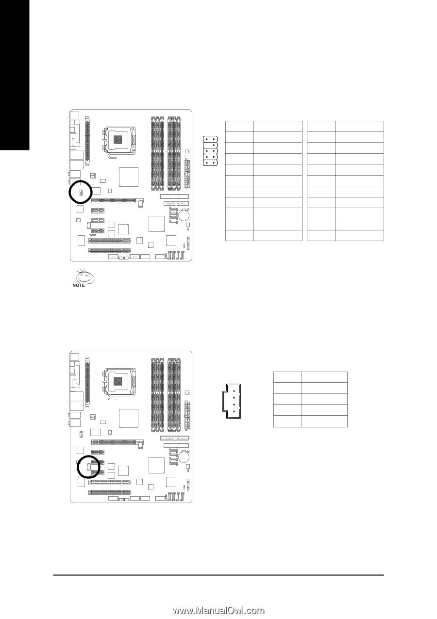
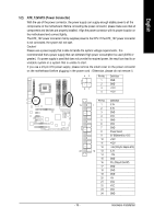
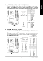
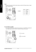
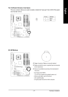
English 13) AZALIA_FP (Front Audio Panel Connector) This connector is supported to connect HD(High Definition) Audio and AC'97 Audio. Check the pin assignment carefully while you connect the audio panel cable, incorrect connection between the cable and connector will make the device unable to work or even damage it. For optional audio panel cable, please contact your local dealer. HD Audio: AC'97 Audio: Pin No. Definition Pin No. Definition 10 91 2 MIC2_L GND 1 MIC 2 GND 3 2 1 4 MIC2_R -ACZ_DET 3 MIC Power 4 NC 5 Line2_R 5 Line Out (R) 6 FSENSE1 6 NC 7 FAUDIO_JD 7 NC 8 No Pin 8 No Pin 9 LINE2_L 9 Line Out (L) 10 FSENSE2 10 NC HD Audio is the default setting for this connector. To enable AC'97 Audio, from BIOS settings, set Front Panel Type under Integrated Peripherals to AC97. 14) CD_IN (CD In Connector) Connect CD-ROM or DVD-ROM audio out to the connector. 1 Pin No. Definition 1 CD-L 2 GND 3 GND 4 CD-R GA-8AENXP-D Motherboard - 24 -
-
 1
1 -
2
-
3
-
4
-
5
-
6
-
7
-
8
-
9
-
10
-
11
-
12
-
13
-
14
-
15
-
16
-
17
-
18
-
 19
19 -
 20
20 -
 21
21 -
 22
22 -
 23
23 -
 24
24 -
 25
25 -
 26
26 -
 27
27 -
 28
28 -
 29
29 -
30
-
31
-
32
-
33
-
34
-
35
-
36
-
37
-
38
-
39
-
40
-
41
-
42
-
43
-
44
-
45
-
46
-
47
-
48
-
49
-
50
-
51
-
52
-
53
-
54
-
55
-
56
-
57
-
58
-
59
-
60
-
61
-
62
-
63
-
64
-
65
-
66
-
67
-
68
-
69
-
70
-
71
-
72
-
73
-
74
-
75
-
76
-
77
-
78
-
79
-
80
-
81
-
82
-
83
-
84
-
85
-
86
-
87
-
88
 |
 |