Gigabyte GA-8SIMLH User Manual
Gigabyte GA-8SIMLH Manual
 |
View all Gigabyte GA-8SIMLH manuals
Add to My Manuals
Save this manual to your list of manuals |
Gigabyte GA-8SIMLH manual content summary:
- Gigabyte GA-8SIMLH | User Manual - Page 1
. M Third-party brands and names are the property of their respective owners. M Please do not remove any labels on motherboard, this may void the warranty of this motherboard. M Due to rapid change in technology, some of the specifications might be out of date beforepublication of this booklet. - Gigabyte GA-8SIMLH | User Manual - Page 2
- Gigabyte GA-8SIMLH | User Manual - Page 3
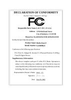
Weg 41, 1F, 20537 Hamburg, Germany declare that the product ( description of the apparatus, system, installation to which it refers) Mother Board GA-8SIMLH is in conformity with (reference to the specification under which conformity is declared) in accordance with 89/336 EEC-EMC Directive Limits - Gigabyte GA-8SIMLH | User Manual - Page 4
City of Industry, CA 91748 Phone/Fax No: (818) 854-9338/ (818) 854-9339 hereby declares that the product Product Name: Motherboard Model Number:GA-8SIMLH Conforms to the following specifications: FCC Part 15, Subpart B, Section 15.107(a) and Section 15.109(a), Class B Digital Device Supplementary - Gigabyte GA-8SIMLH | User Manual - Page 5
GA-8SIMLH P4 Titan-DDR Motherboard USER'S MANUAL Pentium®4 Processor Motherboard Rev. 2101 12M E-8SIM LH -2101 - Gigabyte GA-8SIMLH | User Manual - Page 6
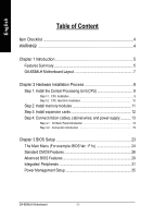
English Table of Content Item Checklist 4 WARNING 4 Chapter 1 Introduction 5 Features Summary 5 GA-8SIMLH Motherboard Layout 7 Chapter 2 Hardware Installation Process 8 Step 1: Install the Central Processing Unit (CPU 9 Step1-1 : CPU Installation 9 Step1-2 : CPU Heat Sink Installation 10 - Gigabyte GA-8SIMLH | User Manual - Page 7
English PnP/PCI Configurations 37 PC Health Status 38 Frequency/Voltage Control 40 Top Performance 42 Load Fail-Safe Defaults 43 Load Optimized Defaults 44 Set Supervisor/User Password 45 Save & Exit Setup 46 Exit Without Saving 47 Chapter 4 Technical Reference 49 Block Diagram ...49 @ - Gigabyte GA-8SIMLH | User Manual - Page 8
English Item Checklist þ The GA-8SIMLH motherboard þ IDE cable x 1/ Floppy cable x 1 þ CD for motherboard driver & utility (TUCD) þ GA-8SIMLH user's manual þ I/O Shield o Quick PC Installation Guide o RAID Manual o 2 Port USB Cable x 1 o 4 Port USB Cable x 1 o SPDIF-KIT x 1 (SPD-KIT) o IEEE 1394 - Gigabyte GA-8SIMLH | User Manual - Page 9
. - Socket 478 for Intel® Micro FC-PGA2 Pentium® 4 processor C hipset Memory I/O Control Slots On-Board IDE On-Board Peripherals Hardware Monitor - Support Intel ® Pentium ® 4 (Northwood, 0.13 m) processor - Intel Pentium®4 400/533MHz FSB - 2nd cache depends on CPU - SiS 651 Host/Memory controller - Gigabyte GA-8SIMLH | User Manual - Page 10
in SiS651 Chipset - PS/2 Keyboard interface and PS/2 Mouse interface - Licensed Award BIOS, 2M bit Flash ROM - Supports Q-Flash - PS/2 Keyboard power on by password - PS/2 Mouse power on - STR(Suspend-To-RAM) - AC ... .etc. "*" for PCB Ver.: 2.01 "**" for PCB Ver.: 2.1 GA-8SIMLH Motherboard - 6 - - Gigabyte GA-8SIMLH | User Manual - Page 11
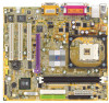
English GA-8SIMLH Motherboard Layout KB_MS USB_LAN ATX_12V COMA SOCKET478 CPU_FAN DIMM_LED ATX FDD GA-8SIMLH VGA LPT F_AUDIO CD_IN AUX_IN MIC_IN LINE_OUT LINE_IN GAME CODEC RT L8100BL W83697HF BIOS COMB SiS 651 AGP DDR1 DDR2 IDE2 IDE1 PCI1 PCI2 PCI3 - Gigabyte GA-8SIMLH | User Manual - Page 12
Unit (CPU) Step 2- Install memory modules Step 3- Install expansion cards Step 4- Connect ribbon cables, cabinet wires, and power supply Step 5- Setup BIOS software Step 6- Install supporting software tools Step 4 Step 1 Step 2 Step 4 Step 3 Step 4 GA-8SIMLH Motherboard - 8 - - Gigabyte GA-8SIMLH | User Manual - Page 13
look for a (golden) cut edge on the CPU upper corner. Then insert the CPU into the socket. M Please make sure the CPU type is supported by the motherboard. M If you do not match the CPU socket Pin 1 and CPU cut edge well, it will cause improper installation. Please change the insert orientation - Gigabyte GA-8SIMLH | User Manual - Page 14
sure the CPU fan power cable is plugged in to the CPU fan connector, this completes the installation. M Please refer to CPU heat sink user's manual for more detail installation procedure. GA-8SIMLH Motherboard - 10 - - Gigabyte GA-8SIMLH | User Manual - Page 15
English Step 2: Install memory modules The motherboard has 2 dual inline memory module (DIMM) sockets. The module can only fit in one direction due to the notch. Memory size can vary between sockets. Support Unbuffered DDR DIMM Sizes type: 64 Mbit (2Mx8x4 banks) 64 Mbit (1Mx16x4 banks) 128 Mbit - Gigabyte GA-8SIMLH | User Manual - Page 16
to its availability, pricing and overall market support. PC2100 DDR memory (DDR266) doubles the Read the related expansion card's instruction document before install the expansion card . 8. Install related driver from the operating system. AGP Card GA-8SIMLH Motherboard Please carefully pull out - Gigabyte GA-8SIMLH | User Manual - Page 17
,mouse, scanner, zip, speaker..etc. Have a standard USB interface. Alsomake sure your OS supports USB controler. If your OS doesnot supportUSB controller, please contact OS vendor for possible patch or driver upgrade. For more information please contact your OS or device(s) vendors. - 13 - Hardw - Gigabyte GA-8SIMLH | User Manual - Page 18
(LPT/COMA/VGA) Parallel Port (25 pin Female) ØThis connector supports 1 standard COM port ,1 Parallel port and 1 VGA port. Device driver, you may connect speaker to Line Out jack, micro phone to MIC Injack. Device like CD-ROM , walkman etc can be connected to Line-In jack. GA-8SIMLH Motherboard - Gigabyte GA-8SIMLH | User Manual - Page 19
English Step 4-2 : Connectors Introduction 3 1 13 12 11 7 4 6 5 17 2 14 16 15 10 8 9 1) CPU_FAN 2) SYS_FAN 3) ATX_12V 4) ATX 5) IDE1/IDE2 6) FDD 7) DIMM_LED 8) PWR_LED 9) F_PANEL 10) BAT1 11) F_AUDIO 12) CD_IN 13) AUX_IN 14) IR 15) F_USB1/F_USB2 16) COMB 17) CI - 15 - Hardw are - Gigabyte GA-8SIMLH | User Manual - Page 20
is essential to prevent the CPU from running under abnormal condition or damaged by overheating.The CPU fan connector supports Max. current up to 600 mA. 2) SYS_FAN (System FAN Connector) Sense 1 +12V/C ontrol VCC GND VCC GND Power Good 5V SB (Stand by +5V) +12V GA-8SIMLH Motherboard - 16 - - Gigabyte GA-8SIMLH | User Manual - Page 21
connect first harddisk to IDE1 and connect CDROM to IDE2. IDE2 IDE1 1 1 6) FDD (Floppy Connector) Ø Please connect the floppy drive ribbon cables to FDD. It supports 360K, 720K, 1.2M, 1.44M and 2.88M bytes floppy disk types. The red stripe of the ribbon cable must be the same side with the Pin1 - Gigabyte GA-8SIMLH | User Manual - Page 22
the pin assignment above. 10) BAT1 (Battery) + GA-8SIMLH Motherboard CAUTI ON v Danger of explosion if battery is incorrectly replaced. v Replace only with the same or equivalent type recommended by the manufacturer. v Dispose of used batteries according to the manufacturer's instructions. - 18 - - Gigabyte GA-8SIMLH | User Manual - Page 23
pin assigment on the cable is the same as the pin assigment on the MB header. To find out if the chassis you are buying support front audio connector, please contact your dealer. 12) CD_IN (CD Audio Line In) C D-R GND 1 C D-L Ø Connect CD-ROM or DVD-ROM audio out to the connector - Gigabyte GA-8SIMLH | User Manual - Page 24
(CASE OPEN) GND 1 Signal Ø This 2 pin connector allows your system to enable or disable the "Case Open"item inBIOS if the system case begin remove. GA-8SIMLH Motherboard - 20 - - Gigabyte GA-8SIMLH | User Manual - Page 25
- 21 - Hardw are Installation Process English - Gigabyte GA-8SIMLH | User Manual - Page 26
English GA-8SIMLH Motherboard - 22 - - Gigabyte GA-8SIMLH | User Manual - Page 27
English Chapter 3 BIOS Setup BIOS Setup is an overview of the BIOS Setup Program. The program that allows users to modify the basic system configuration. This type of information is stored in battery-backed CMOS RAM so that it retains the Setup information when the power is turned off. ENTERING - Gigabyte GA-8SIMLH | User Manual - Page 28
the appropriate keys to use and the possible selections for the highlighted item. To exit the Help Window press . The Main Menu (For example: BIOS Ver. : F1o) Once you enterAward BIOS This setup page includes all the items of Award special enhanced features. GA-8SIMLH Motherboard - 24 - - Gigabyte GA-8SIMLH | User Manual - Page 29
English l Integrated Peripherals This setup page includes all onboard peripherals. l Power Manag ement Setup This setup page includes all the items of Green function features. l PnP/PCI Configurations This setup page includes all the configurations of PCI & PnP ISA resources. l PC Health Status - Gigabyte GA-8SIMLH | User Manual - Page 30
e None None None None y ear Sun. to Sat. Driv e A Driv e B Floppy 3 Mode Support Halt On Base Memory Ex tended Memory Total Memory 1.44M, 3.5 in. None Disabled All, But Key board 640K 130048K imum allow ed in the month) The y ear, from 1999 through 2098 GA-8SIMLH Motherboard - 26 - - Gigabyte GA-8SIMLH | User Manual - Page 31
identifies the types of hard disk from driveC to F that has been installed in the computer. There are two types: auto type, and manual type. Manual type is user-definable; Auto type which will automatically detect HDD type. Note that the specifications of your drive must match with the drive table - Gigabyte GA-8SIMLH | User Manual - Page 32
Mode Support (for motherboard, or 640 K for systems with 640 K or more memory installed on the motherboard. Extended Memory The BIOS determines how much extended memory is present during the POST. This is the amount of memory located above 1 MB in the CPU's memory address map. GA-8SIMLH Motherboard - Gigabyte GA-8SIMLH | User Manual - Page 33
English Advanced BIOS Features CMOS Setup Utility -Copy right (C) 1984-2002 Aw ard Softw are First Boot Dev ice Adv anced BIOS Features [Floppy ] Item Help Second Boot Dev ice [HDD-0] Menu Lev el u Third Boot Dev ice [CDROM] Select Boot Dev ice Boot Up Floppy Seek [Disabled] priority - Gigabyte GA-8SIMLH | User Manual - Page 34
pe of floppy disk driv e by track number. Note that there w ill not be any w arning message if the driv e installed is 360 K. (Default v alue) GA-8SIMLH Motherboard - 30 - - Gigabyte GA-8SIMLH | User Manual - Page 35
Auto-detect IDE AC97 Audio [Enabled] cable ty pe Sy stem Share Memory Size [32MB] USB Controller [Enabled] [ATA66/100/133] USB Legacy Support [Disabled] Set Conductor cable On Board LAN Function [Enabled] to ATA66/100/133(80-pins) Init Display First Onboard Serial Port A [AGP] [3F8 - Gigabyte GA-8SIMLH | User Manual - Page 36
Disable USB Controller. C USB Legacy Support 8Enabled Enable USB Legacy Support. 8Disabled Disable USB Legacy Support. (Default v alue) C On Board LAN Function 8Disabled 8Enabled Disable this function. Enable Onboard Lan Chip function. (Default Value) GA-8SIMLH Motherboard - 32 - - Gigabyte GA-8SIMLH | User Manual - Page 37
English CInit Display First 8AGP Set Init Display First to AGP. (Default v alue) 8PCI Set Init Display First to PCI. C Onboard Serial Port A 8Auto BIOS w ill automatically setup the port A address. 83F8/IRQ4 Enable onboard Serial port A and address is 3F8. (Default v alue) 82F8/IRQ3 Enable - Gigabyte GA-8SIMLH | User Manual - Page 38
330.(Default Value) 8Disabled Disable this function. CMidi Port IRQ 85 810 Set Midi Port IRQ to 5. Set Midi Port IRQ to 10. (Default Value) GA-8SIMLH Motherboard - 34 - - Gigabyte GA-8SIMLH | User Manual - Page 39
English Power Management Setup CMOS Setup Utility -Copy right (C) 1984-2002 Aw ard Softw are Pow er Management Setup ACPI Suspend Ty pe S1(POS) Item Help Soft-Off by PWR_BTTN Off Menu Lev el u Sy stem After AC Back Off [S1] IRQ [3-7, 9-15], NMI Enabled Set suspend ty pe to - Gigabyte GA-8SIMLH | User Manual - Page 40
(S1): a. If use single color LED, pow er LED w ill turn off. b. If use dual color LED, pow er LED w ill turn to another color. GA-8SIMLH Motherboard - 36 - - Gigabyte GA-8SIMLH | User Manual - Page 41
English PnP/PCI Configurations CMOS Setup Utility -Copy right (C) 1984-2002 Aw ard Softw are PnP/PCI Configurations PCI 1 IRQ Assignment Auto Item Help PCI 2 IRQ Assignment Auto Menu Lev el u PCI 3 IRQ Assignment Auto higf: Mov e Enter:Select +/-/PU/PD:Value F10:Sav e ESC:Ex it F1: - Gigabyte GA-8SIMLH | User Manual - Page 42
status automatically . C Current System/CPU Temperature 8Detect Sy stem/CPU Temp. automatically. C Current CPU/SYSTEM FAN Speed (RPM) 8Detect CPU/SYSTEM Fan speed status automatically . GA-8SIMLH Motherboard - 38 - - Gigabyte GA-8SIMLH | User Manual - Page 43
English C CPU Warning Temperature 860°C / 140°F Monitor CPU Temp. at 60°C / 140°F. 870°C / 158°F Monitor CPU Temp. at 70°C / 158°F. 880°C / 176°F Monitor CPU Temp. at 80°C / 176°F. 890°C / 194°F Monitor CPU Temp. at 90°C / 194°F. 8Disabled Disable this function.(Default v alue) C CPU FAN - Gigabyte GA-8SIMLH | User Manual - Page 44
DRAM module, please set "DRAM Clock(MHz)" to 333. Incorrect using it may cause y our sy stem broken. For pow er End-User use only ! GA-8SIMLH Motherboard - 40 - - Gigabyte GA-8SIMLH | User Manual - Page 45
English C AGP Clock (MHz) 8Please set AGP Clock according to y our requirement. Incorrect using it may cause y our sy stem broken. For pow er End-User use only ! C PCI Clock (MHz) 8Please set PCI Clock according to y our requirement. Incorrect using it may cause y our sy stem broken. For pow er End - Gigabyte GA-8SIMLH | User Manual - Page 46
you wish to maximize the performance of your system, set "Top Performance" as "Enabled". 8Disabled Disable this function. (Default Value) 8Enabled Enable Top Performance function. GA-8SIMLH Motherboard - 42 - - Gigabyte GA-8SIMLH | User Manual - Page 47
English Load Fail-Safe Defaults CMOS Setup Utility -Copy right (C) 1984-2002 Aw ard Softw are }Standard CMOS Features Top Performance }Adv anced Chipset Features Load Fail-Safe Defaults }Integrated Peripherals Load Optimized Defaults }Pow er Management SLeotuapd Fail-Safe DefauSletst?Su(pYe - Gigabyte GA-8SIMLH | User Manual - Page 48
Figure 11: Load Optimized Defaults Load Optimized Defaults Selecting this field loads the factory defaults for BIOS and Chipset Features which the system automatically detects. GA-8SIMLH Motherboard - 44 - - Gigabyte GA-8SIMLH | User Manual - Page 49
English Set Supervisor/User Password CMOS Setup Utility -Copy right (C) 1984-2002 Aw ard Softw are }Standard CMOS Features Top Performance }Adv anced BIOS Features Load Fail-Safe Defaults }Integrated Peripherals Load Optimized Defaults }Pow er Management Setup }PnP/PCI ConfigurationEsnter - Gigabyte GA-8SIMLH | User Manual - Page 50
: Sav e & Ex it Setup Type "Y"will quit the Setup Utility and save the user setup value to RTC CMOS. Type "N"will return to Setup Utility. GA-8SIMLH Motherboard - 46 - - Gigabyte GA-8SIMLH | User Manual - Page 51
English Exit Without Saving CMOS Setup Utility -Copy right (C) 1984-2002 Aw ard Softw are }Standard CMOS Features Top Performance }Adv anced BIOS Features Load Fail-Safe Defaults }Integrated Peripherals Load Optimized Defaults }Pow er Management Setup Set Superv isor Passw ord }PnP/PCI - Gigabyte GA-8SIMLH | User Manual - Page 52
English GA-8SIMLH Motherboard - 48 - - Gigabyte GA-8SIMLH | User Manual - Page 53
English RCehvaispitoenr H4isTtoercyhnical Reference Block Diagram AGP 2X/4X AGPCLK (66M Hz) VGA Port 3 PCI RJ45 RTL81 00BL Pentium 4 Socket 478 CPU CPUCLK+/- (100/133MHz) System Bus 400/533M Hz DDR SiS 651 200/266/333M Hz ZCLK (66MHz) HCLK+/- (100/133MHz) 66 MHz 33 MHz 48 MHz 14.318 MHz - Gigabyte GA-8SIMLH | User Manual - Page 54
BIOS update software, it's a Windows utility. With the help of "@BIOS', Gigabyte's motherboard, you could find this amazing software in the attached driver CD. But please remember,connected to internetat first,then you could have a internetBIOS update from your Gigabyte @BIOS. GA-8SIMLH Motherboard - Gigabyte GA-8SIMLH | User Manual - Page 55
.This wonderfulsoftware is nowfree bundled in Gigabyte motherboard attached in driver CD. Users may make a test drive of "EasyTune 4" to find out more amazing features by themselves. *Some Gigabyte products are notfullysupported byEasyTune 4. Please find the products supported list in the web site - Gigabyte GA-8SIMLH | User Manual - Page 56
: Q-Flash Utility V3.06 SST 39SF020 /256K Yes Load BIOS from Floppy Save BIOS to Floppy Enter: Run SpaceBar:Change Value ESC: Reset h/i: Select Item GA-8SIMLH Motherboard - 52 - - Gigabyte GA-8SIMLH | User Manual - Page 57
English Load BIOS From Floppy !In the A:drive, insert the "BIOS" diskette, then Press Enter to Run. 1 File(s) found XXXX.XX 256K Total Size: 1.39M F5: Refresh Free Size: 1.14M DEL: Delete ESC: Return Main Where XXXX.XX is name of the BIOS file. !Press Enter to Run. Are you sure to update - Gigabyte GA-8SIMLH | User Manual - Page 58
www.shareware.cnet.com STEP 2: Make a DOS boot diskette. (See example: Windows 98 O.S.) Beware: Windows ME/2000 are notallowed to make a DOS bootdiskette. (1) With an available floppy icon from Desktop, then click "3.5 diskette (A)" and rightclick to select "Format(M)" GA-8SIMLH Motherboard - 54 - - Gigabyte GA-8SIMLH | User Manual - Page 59
English (2) Selectthe "Quick (erase)" for FormatType,and pick both "Displaysummary when finished" and "Copy system files", after thatpress "Start". That will formatthe floppyand transfer the needed system files to it. Beware: This procedure will erase all the prior data on that floppy, so please - Gigabyte GA-8SIMLH | User Manual - Page 60
English STEP 3: Download BIOS and BIOS utility program. (1) Please go to Gigabyte website http://www.gigabyte.com.tw/index.html, and click "Support". (2) From Supportzone, click the "Motherboards BIOS & Drivers". GA-8SIMLH Motherboard - 56 - - Gigabyte GA-8SIMLH | User Manual - Page 61
English (3) We use GA-7VTXmotherboard as example.Please selectGA-7VTX by Modelor Chipsetoptional menu to obtain BIOS flash files. (4) Selectan appropriate BIOS version (Forexample: F4), and click to download - Gigabyte GA-8SIMLH | User Manual - Page 62
English (5) Atthis time the screen shows the following picture, please click "Extract" button to unzip the files. (6) Please extract the download files into the clean bootable floppy disk A mentioned in STEP 2,and press "Extract". GA-8SIMLH Motherboard - 58 - - Gigabyte GA-8SIMLH | User Manual - Page 63
. Please press keyto enter BIOS setup main menu when system is bootup. Ame r ican R e le a se :0 9 /1 6 /9 9 Meg a tre n d s AMIBIOS ( C) 19 9 9 Ame ri ca n Me ga tr en d 7 VTX F1 Ch eck Syste m Hea lth OK AMD- Ath lo n( tm) Pr oce ssor -90 0MHz Ch ecki ng N VR AM... 2621 - Gigabyte GA-8SIMLH | User Manual - Page 64
(Shift)F2 : Change Color F5: Old Values F6: Load BIOS Defaults F7: Load Setup Defaults F10:Save & Exit Save Data to CM OS & Exit SETUP GA-8SIMLH Motherboard - 60 - - Gigabyte GA-8SIMLH | User Manual - Page 65
English STEP 5: BIOS flashing. (1) After the system boot from floppy disk, type "A:\> dir/w" and press "Enter" to check the entire files in floppy A. Then type the "BIOS flash utility" and "BIOS file" after A:\>. In this case you have to type "A:\> Flash841 7VTX.F4" and then press "Enter". - Gigabyte GA-8SIMLH | User Manual - Page 66
] to continue Or [Esc] to cancel? (4) The BIOS flash completed. Please press [ESC] to exit Flash Utility. EXIT? [Enter] to continue Or [Esc] to cancel? GA-8SIMLH Motherboard - 62 - - Gigabyte GA-8SIMLH | User Manual - Page 67
floppy diskette from floppy drive, and then restartthe system. The bootup screen will indicate your motherboard model and currentBIOSversion. Ame r ican R e le a se :0 9 /1 6 /9 9 Meg a tre n d s AMIBIOS ( C) 19 9 9 Ame ri ca n Me ga tr en d 7 VTX F4 Ch eck Syste m Hea lth OK AMD- Ath lo n( tm) Pr - Gigabyte GA-8SIMLH | User Manual - Page 68
: Load BIOS Defaults F7: Load Setup Defaults F10:Save & Exit Save Data to CM OS & Exit SETUP (4) Congratulate you have accomplished the BIOS flash procedure. GA-8SIMLH Motherboard - 64 - - Gigabyte GA-8SIMLH | User Manual - Page 69
recommend thatyou used Gigabyte @BIOSTM program to flash BIOS. Press "Tools" icon. 2.Click "@BIOS Writer ver.1.08q". 1.Click "Gigabyte Utilities". (1) c. Select @BIOSTM sever d. Selectthe exactmodelname on your motherboard e. System will automatically download and update the BIOS. - - Gigabyte GA-8SIMLH | User Manual - Page 70
internetor anyother methods (such as: 8SIMLH.F 1). e. Complete update processfollowing the instruction. III. Save BIOS In the Gigabyte's web site fordownloading and updating itaccording to method II. d. Please note thatanyinterruption during updating willcause system unbooted GA-8SIMLH Motherboard - Gigabyte GA-8SIMLH | User Manual - Page 71
- 67 - Technical Reference English - Gigabyte GA-8SIMLH | User Manual - Page 72
English GA-8SIMLH Motherboard - 68 - - Gigabyte GA-8SIMLH | User Manual - Page 73
are shown in Windows XP (TUCD driver version 2.1) Appendix A: SiS 650/650GX/650GL/651 Chipset Driver Installation A. SiS 650 VGA Driver: Insert the driver CD-title that came with your motherboard into your CD-ROM driver, the driver CD-title will auto start and show the installation guide. If not - Gigabyte GA-8SIMLH | User Manual - Page 74
English 5.Click "Next". (5) (6) 6.Click "Finish" to restart computer. (7) GA-8SIMLH Motherboard - 70 - - Gigabyte GA-8SIMLH | User Manual - Page 75
B. SiS AGP Driver: Insert the driver CD-title that came with your motherboard into your CD-ROM driver, the driver CD-title will auto start and show the installation guide. If not, please double click the CD-ROM device icon in "My computer", and execute the setup.exe. 1.Click "SiS AGP Driver " item - Gigabyte GA-8SIMLH | User Manual - Page 76
devices support. Please also note that Microsoft® USB2.0 driver is currently supported by Windows XP and Windows 2000 only. Once we get the latest SiS® USB2.0 driver for Windows 98 and Windows ME, we will put the driver on GIGABYTE website asap. (http://www.gigabyte.com.tw). GA-8SIMLH Motherboard - Gigabyte GA-8SIMLH | User Manual - Page 77
English Appendix B: SiS 7012 Sound Driver * Insert the driver CD-title that came with your motherboard into your CD-ROM driver, the driver CD-title will auto start and show the installation guide. If not, please double click the CD-ROM device icon in "My computer", and execute the setup.exe. Press - Gigabyte GA-8SIMLH | User Manual - Page 78
installation guide. If not, please double click the CD-ROM device icon in "My computer", and execute the setup.exe. Press "Audio" icon. 1.Click "Realtek AC'97 Audio Driver" item. (1) 2.Click "Next". (2) 3.Click "Finish" to restart computer. (3) (4) "**" for PCB Ver.: 2.1 GA-8SIMLH Motherboard - Gigabyte GA-8SIMLH | User Manual - Page 79
English RApepvenisdiixoCn: RHeaislTteok r8y100/8139 LAN Driver Insert the driver CD-title that came with your motherboard into your CD-ROM driver, the driver CD-title will auto start and show the installation guide. If not, please double click the CD-ROM device icon in "My computer", and execute - Gigabyte GA-8SIMLH | User Manual - Page 80
show the installation guide. If not, please double click the CD-ROM device icon in "My computer", and execute the setup.exe. Press "Tools" icon. 1.Click "Gigabyte Utilities". (1) 2.Click "EasyTune 4 Trial Version". (2) 3.Click "Next". (3) 4.Click "Next". (4) (5) GA-8SIMLH Motherboard 5.Click - Gigabyte GA-8SIMLH | User Manual - Page 81
English Appendix E: Acronyms Acronyms Meaning ACPI Advanced Configuration and Power Interface APM Advanced Power Management AGP Accelerated Graphics Port AMR Audio Modem Riser ACR Advanced Communications Riser BIOS Basic Input / Output System CPU Central Processing Unit CMOS - Gigabyte GA-8SIMLH | User Manual - Page 82
Power-On Self Test Peripheral Component Interconnect Rambus in-line Memory Module Special Circumstance Instructions Single Edge Contact Cartridge Static Random Access Memory Symmetric Multi-Processing System Management Interrupt Universal Serial Bus Voltage ID GA-8SIMLH Motherboard - 78 - - Gigabyte GA-8SIMLH | User Manual - Page 83
English & Technical Support/RMA Sheet Customer/Country: Contact Person: Company: E-mail Add. : Model name/Lot Number: BIOS version: ROM Modem Network AMR / CNR Keyboard Mouse Power supply Other Device Phone No.: PCB revision: Driver/Utility: Problem Description: & - 79 - Appendix
-
 1
1 -
 2
2 -
 3
3 -
 4
4 -
 5
5 -
 6
6 -
 7
7 -
8
-
9
-
10
-
11
-
12
-
13
-
14
-
15
-
16
-
17
-
18
-
19
-
20
-
21
-
22
-
23
-
24
-
25
-
26
-
27
-
28
-
29
-
30
-
31
-
32
-
33
-
34
-
35
-
36
-
37
-
38
-
39
-
40
-
41
-
42
-
43
-
44
-
45
-
46
-
47
-
48
-
49
-
50
-
51
-
52
-
53
-
54
-
55
-
56
-
57
-
58
-
59
-
60
-
61
-
62
-
63
-
64
-
65
-
66
-
67
-
68
-
69
-
70
-
71
-
72
-
73
-
74
-
75
-
76
-
77
-
78
-
79
-
80
-
81
-
82
-
83
 |
 |

M
The author assumes no responsibility for any
errors or omissions that may appear in this
document nor does the author make a
commitment to update the information
contained herein.
M
Third-party brands and names are the
property of their respective owners.
M
Please do not remove any labels on
motherboard, this may void the warranty of
this motherboard.
M
Due to rapid change in technology, some of
the specifications might be out of date
beforepublication of this booklet.