Gigabyte GA-8SIMLH User Manual - Page 21
IDE1/ IDE2 [IDE1 / IDE2 ConnectorPrimary/Secondary], FDD Floppy Connector, DIMM_LED, PWR_LED
 |
View all Gigabyte GA-8SIMLH manuals
Add to My Manuals
Save this manual to your list of manuals |
Page 21 highlights
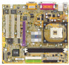
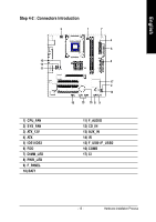
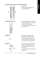
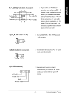
English 5) IDE1/ IDE2 [IDE1 / IDE2 Connector(Primary/Secondary)] Ø Important Notice: Please connect first harddisk to IDE1 and connect CDROM to IDE2. IDE2 IDE1 1 1 6) FDD (Floppy Connector) Ø Please connect the floppy drive ribbon cables to FDD. It supports 360K, 720K, 1.2M, 1.44M and 2.88M bytes floppy disk types. The red stripe of the ribbon cable must be the same side with the Pin1. 1 7) DIMM_LED +- 8) PWR_LED 1 MPD+ MPD- MPD- Ø Do not remove memory modules while DIMM LED is on. It might cause short or other unexpected damages due to the 2.5V stand by voltage. Remove memory modules only when AC Power cord is disconnected. Ø PWR_LED is connect with the system power indicator to indicate whether the system is on/off. It will blink when the system enters suspend mode. If you use dual color LED, power LED will turn to another color. - 17 - Hardw are Installation Process
-
 1
1 -
2
-
3
-
4
-
5
-
6
-
7
-
8
-
9
-
10
-
11
-
12
-
13
-
14
-
15
-
 16
16 -
 17
17 -
 18
18 -
 19
19 -
 20
20 -
 21
21 -
 22
22 -
 23
23 -
 24
24 -
 25
25 -
 26
26 -
27
-
28
-
29
-
30
-
31
-
32
-
33
-
34
-
35
-
36
-
37
-
38
-
39
-
40
-
41
-
42
-
43
-
44
-
45
-
46
-
47
-
48
-
49
-
50
-
51
-
52
-
53
-
54
-
55
-
56
-
57
-
58
-
59
-
60
-
61
-
62
-
63
-
64
-
65
-
66
-
67
-
68
-
69
-
70
-
71
-
72
-
73
-
74
-
75
-
76
-
77
-
78
-
79
-
80
-
81
-
82
-
83
 |
 |
