Gigabyte GA-970A-D3 Manual - Page 24
SATA3_0/1/2/3/4/5 SATA 6Gb/s Connectors, BAT Battery
 |
View all Gigabyte GA-970A-D3 manuals
Add to My Manuals
Save this manual to your list of manuals |
Page 24 highlights
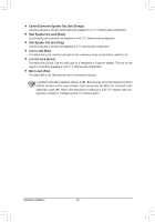
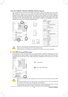
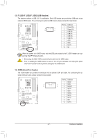
7) SATA3_0/1/2/3/4/5 (SATA 6Gb/s Connectors) The SATA connectors conform to SATA 6Gb/s standard and are compatible with SATA 3Gb/s and SATA 1.5Gb/s standard. Each SATA connector supports a single SATA device. The AMD SB950 South Bridge supports RAID 0, RAID 1, RAID 5, RAID 10, and JBOD. Refer to Chapter 5, "Configuring SATA Hard Drive(s)," for instructions on configuring a RAID array. G.QBOFM G.QBOFM GP.inQBNOoF. M Definition SATA3_0 7 SATA3_2 SATA3_4 1 1 GND 2 TXP 3 TXN 7 1 4 GND SATA3_1 SATA3_3 SATA3_5 5 RXN 6 RXP 7 GND UG DEBUG T PORT •• A RAID 0 or RAID 1 configuration requires at least two hard drives. If more than two hard drives are to be used, the total number of hard drives must be an even number. Please connect the L-shaped end of •• A RAID 5 configuration requires at least three hard drives. the SATA cable to your SATA hard (The total number of hard drives ••does not have to be an drive. even number.) •• A RAID 10 configuration requires four hard drives. 8) BAT (Battery) The battery provides power to keep the values (such as BIOS configurations, date, and time information) in the CMOS when the computer is turned off. Replace the battery when the battery voltage drops to a low level, or the CMOS values may not be accurate or may be lost. You may clear the CMOS values by removing the battery: 1. Turn off your computer and unplug the power cord. 2. Gently remove the battery from the battery holder and wait for one minute. (Or use a metal object like a screwdriver to touch the positive and negative terminals of the battery holder, making them short for 5 seconds.) 3. Replace the battery. 4. Plug in the power cord and restart your computer. •• Always turn off your computer and unplug the power cord before replacing the battery. •• Replace the battery with an equivalent one. Danger of explosion if the battery is replaced with an incorrect model. •• Contact the place of purchase or local dealer if you are not able to replace the battery by yourself or uncertain about the battery model. •• When installing the battery, note the orientation of the positive side (+) and the negative side (-) of the battery (the positive side should face up). •• Used batteries must be handled in accordance with local environmental regulations. Hardware Installation - 24 -
-
 1
1 -
2
-
3
-
4
-
5
-
6
-
7
-
8
-
9
-
10
-
11
-
12
-
13
-
14
-
15
-
16
-
17
-
18
-
 19
19 -
 20
20 -
 21
21 -
 22
22 -
 23
23 -
 24
24 -
 25
25 -
 26
26 -
 27
27 -
 28
28 -
 29
29 -
30
-
31
-
32
-
33
-
34
-
35
-
36
-
37
-
38
-
39
-
40
-
41
-
42
-
43
-
44
-
45
-
46
-
47
-
48
-
49
-
50
-
51
-
52
-
53
-
54
-
55
-
56
-
57
-
58
-
59
-
60
-
61
-
62
-
63
-
64
-
65
-
66
-
67
-
68
-
69
-
70
-
71
-
72
-
73
-
74
-
75
-
76
-
77
-
78
-
79
-
80
-
81
-
82
-
83
-
84
-
85
-
86
-
87
-
88
-
89
-
90
-
91
-
92
-
93
-
94
-
95
-
96
 |
 |
