Gigabyte GA-9IVDT User Manual
Gigabyte GA-9IVDT Manual
 |
View all Gigabyte GA-9IVDT manuals
Add to My Manuals
Save this manual to your list of manuals |
Gigabyte GA-9IVDT manual content summary:
- Gigabyte GA-9IVDT | User Manual - Page 1
GA-9IVDT Dual XeonTM (Nocona/Iwindale) Processor Motherboard USER'S MANUAL Dual XeonTM (Nocona/Iwindale)Processor Motherboard Rev. 1102 12ME-9IVDT-1102 - Gigabyte GA-9IVDT | User Manual - Page 2
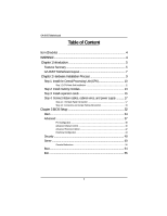
5 GA-9IVDT Motherboard Layout 7 Chapter 2 Hardware Installation Process 9 Step 1: Install the Central Processing Unit (CPU 10 Step 1-2:CPU Heat Sink Installation 11 Step 2: Install memory modules 13 Step 3: Install expansion cards 16 Step 4: Connect ribbon cables, cabinet wires, and power - Gigabyte GA-9IVDT | User Manual - Page 3
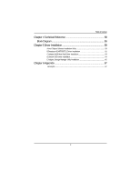
Reference 58 Block Diagram 58 Chapter 5 Driver Installation 59 A.Intel Chipset Software Installation Utility 59 B.Broadcom BCM5705/5721 Driver Installation 61 C.Adapetc 8130 Host Raid Driver Installation 63 D.DirectX 9.0C Driver Installation 64 E.Adaptec Storage Manager Utility Installation - Gigabyte GA-9IVDT | User Manual - Page 4
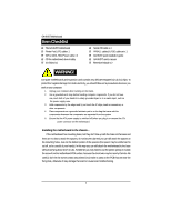
GA-9IVDT motherboard Printer Port (LPT) cable x 1 IDE to SATA HDD Power cable x 2 CD for motherboard driver & utility I/O Shield x1 Serial ATA cable x 4 PATA ( 1 cables) & FDD cable set x 1 GA-9IVDT quick installation guide GA-9IVDT user's manual Retention Module x 2 WARNING! Computer motherboards - Gigabyte GA-9IVDT | User Manual - Page 5
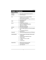
x 10.5cm CEB size form factor, 8 layers PCB. y GA-9IVDT Motherboard: CPU Chipset Memory I/O Control Slots On-Board IDE y Dual socket 604 for Intel® Xeon(Nocona/Iwindale) processor suopprts 3.6 GB and upper y Intel® Xeon (Nocona/Irwindale) CPUs supports 800 MHz FSB y L2 cache depend on CPU y Intel - Gigabyte GA-9IVDT | User Manual - Page 6
background rebuilds y Features LBA and Extended Interrupt 13 drive translation in controller onboard BIOS y Adaptec® AIC-8130 chipset supports SATAII interface y Build in Intel® 6300ESB chipset y RAID 0,1,5,10 are supported when ZCR card is populated. (Optional) On-Board LAN On-Board USB 2.0 PS - Gigabyte GA-9IVDT | User Manual - Page 7
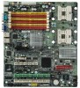
GA-9IVDT Motherboard Layout O N M S L KJ I V T 㕼㕧 㖅㕧 㕺㖀㕣 㖅㖃㕲㕢 W 㖅㕡 㕼㕡 㖅㕧 㕼㕧 E X 㖅㕡 㕼㕡 㖅㕧 㕼㕧 㖅㕡 㕼㕡 㖅㕧 㕼㕧 㖅㕡 㕼㕡 F G 㕹㕴㕵㕡 㕱㖄㖈㕢 1 㖇㕿㕼㕡 㖇㕿㖂㕡 6 㕼㖀㖄㕡 2Y Z 㕺㖀㕡 H C 7 34 5 Q 㕳㖀㖅㕡 B 10 11 - Gigabyte GA-9IVDT | User Manual - Page 8
English GA-9IVDTMotherboard A. CPU1 ( Power Fan) S. SYS_FAN2 (System Fan) T. SYS_FAN3 (System Fan) U. ATX1Power connector) V. ATX2 (Power connector) W. PCI-X_2 (ZCR Slot) X. PCI-X_1 Y. PCI1 Z. PCI_E_x4 (PCI-E x4 Slot) ** Note: This device is reserved for Adaptec AIC-8140 chipset. (Supports - Gigabyte GA-9IVDT | User Manual - Page 9
Installation Process To set up your computer, you must complete the following steps: Step 1- Install the Central Processing Unit (CPU) Step 2- Install memory modules Step 3- Install expansion cards Step 4- Connect ribbon cables, cabinet wires, and power supply Step3 Step 2 Step4 Step4 Step4 - Gigabyte GA-9IVDT | User Manual - Page 10
(CPU) Before installing the processor , adhere to the following warning: If you do not match the CPU socket Pin 1 and CPU cut edge well, it will cause improper installation. Please change the insert orientation. Please make sure the CPU type is supported by the motherboard. 1. Angling the rod to - Gigabyte GA-9IVDT | User Manual - Page 11
cooling fan, you might pull the processor out of the CPU socket alone with the cooling fan, and might damage the processor. To avoid this from happening, CPU fan power cable is plugged in to the CPU fan connector, this completes the installation. Please refer to CPU heat sink user's manual for more - Gigabyte GA-9IVDT | User Manual - Page 12
English GA-9IVDTMotherboard 3. Fasten the heatsink supporting-base onto the CPU socket on the mainboard. 4. Make sure the CPU fan is plugged to the CPU fan connector, than install complete. 12 - Gigabyte GA-9IVDT | User Manual - Page 13
Step 2: Install memory modules Hardware Installation Process Before installing the processor and heatsink, adhere to the following orientation. The motherboard has 6 dual inline memory module (DIMM) sockets. The BIOS will automatically detects memory type and size. To install the memory module, - Gigabyte GA-9IVDT | User Manual - Page 14
English GA-9IVDTMotherboard 1. The DIMM slot has a notch, so the DIMM memory module can only fit in one direction. 2. Insert the DIMM memory module vertically into the DIMM slot. Then push it down. Please note that DIMM must be populated in order starting at the nearest slot from the ATX power. 3. - Gigabyte GA-9IVDT | User Manual - Page 15
English GA-9IVDTMotherboard Table 1. Supported DIMM Module Type Technology 256MB 512MB 1GB Organization 8MB x 8 x 4 bks 16MB x 4 x 4bks 16MB x 8 x 4bks 32MB x 4 x 4bks 32MB x 8 x 4bks 64MB x 4 x 4bks Table 2. DIMM Placement DDR2-400 - Gigabyte GA-9IVDT | User Manual - Page 16
into expansion slot in motherboard. 4. Be sure the metal contacts on the card are indeed seated in the slot. 5. Replace the screw to secure the slot bracket of the expansion card. 6. Replace your computer's chassis cover. 7. Power on the computer, if necessary, setup BIOS utility of expansion card - Gigabyte GA-9IVDT | User Manual - Page 17
\ \ [ 17 GA-9IVDTMotherboard Step 4: Connect ribbon cables, cabinet wires, and power supply Step 4-1 : I/O Back Panel Introduction 㕺㖀㕣 㖅㖃㕲㕢 㕢 㕹㕴㕵㕡 㖇㕿㕼㕡 㖇㕿㖂㕡 㕼㖀㖄㕡 㕳㖀㖅㕡 X Y Z 㕴㕴㖂㕡 㕱㖄㖈㕡 㕴㕴㖂㕢 㕳㕿㕽㕡 㖅㖃㕲㕡 - Gigabyte GA-9IVDT | User Manual - Page 18
, scanner, zip, speaker...etc. have a standard USB interface. Also make sure your OS supports USB controller. If your OS does not support USB controller, please contact OS vendor for possible patch or driver upgrade. For more information please contact your OS or device(s) vendors. Z/[ Serial Port - Gigabyte GA-9IVDT | User Manual - Page 19
English GA-9IVDTMotherboard Step 4-2 :Connectors and Jumper Setting Introduction J IT Q P D G R 1 V H 㕺㖀㕣 㖅㖃㕲㕢 㕼㖀㖄㕡 㖇㕿㖂㕡 㖇㕿㕼㕡 㕴㕴㖂㕢 㕳㕿㕽㕡 㖅㖃㕲㕡 㕺㖀㕡 U M 㕱㖄㖈㕡 A W XN S 㕹㕴㕵㕡 Z C Y 㕳㖀㖅㕡 㕴㕴㖂㕡 K 㕱㖄㖈㕢 - Gigabyte GA-9IVDT | User Manual - Page 20
and other related devices are firmly connected to the mainboard. B ) ATX2 (ATX Power Connector) 13 1 24 12 Connector Introduction PIN No. 1 2 3 4 5 6 7 8 9 10 11 12 13 14 15 16 17 18 19 20 21 22 23 24 Definition +3.3V +3. - Gigabyte GA-9IVDT | User Manual - Page 21
English GA-9IVDTMotherboard C) IDE1 Connector Please connect first harddisk to IDE1. The red stripe of the ribbon 40 D) FDD1 (Floppy Connector) Please connect the floppy drive ribbon cables to FDD. It supports 360K,720K,1.2M,1.44M and 2.88Mbytes floppy disk types. The red stripe of the ribbon cable - Gigabyte GA-9IVDT | User Manual - Page 22
Connector Introduction E / F ) MV_SATA1/SATA2/SATA3SATA4 (Serial ATA Connectors) You can connect the Serial ATA device to this connector, it provides you high speed transfer rates (150MB/sec). 㕳㕿㕽㕡 㖅㖃㕲㕡 㕴㕴㖂㕢 㕼㖀㖄㕡 㕱㖄㖈㕡 㕺㖀㕣 㖇㕿㖂㕡 㖇㕿㕼㕡 㖅㖃㕲㕢 - Gigabyte GA-9IVDT | User Manual - Page 23
English GA-9IVDTMotherboard H ) USB2 (Front USB Connector ) Be careful with the polarity of 㕼㕧 㕼㕡 㕼㕧 㕼㕡 㕴㕴㖂㕡 㕴㕴㖂㕢 㕳㕿㕽㕡 㖅㖃㕲㕡 㕱㖄㖈㕡 㕺㖀㕡 12 9 10 Pin No. 1 2 3 4 5 6 7 8 9 10 Definition Power Power USB DxUSB DyUSB Dx+ USB Dy+ GND GND No Pin OC I ) WOR1 (Wake on Ring - Gigabyte GA-9IVDT | User Manual - Page 24
GA-9IVDTMotherboard J ) WOL1 (Wake on LAN) This connector allows the remove servers to manage the system that installed this mainboard via your network adapter which also supports or damaged by overheating.The CPU fan connector supports Max. current up to 1A . 㕺㖀㕣 㕼㖀㖄㕡 - Gigabyte GA-9IVDT | User Manual - Page 25
English GA-9IVDTMotherboard M) PWR_FAN1 (Power Fan Connector) This connector allows you to link with the cooling fan on the system case to lower the system temperature. 㕼㖀㖄㕡 㖇㕿㖂㕡 㕺㖀㕣 㖇㕿㕼㕡 㕳㖀㖅㕡 㕴㕴㖂㕡 㕴㕴㖂㕢 㕳㕿㕽㕡 㖅㖃㕲㕡 㕱㖄㖈㕡 Pin No. Definition - Gigabyte GA-9IVDT | User Manual - Page 26
P ) LPT1 &Please connect the printer device via this connector. 㕳㕿㕽㕡 㖅㖃㕲㕡 㕴㕴㖂㕢 㕼㖀㖄㕡 㖇㕿㖂㕡 㕺㖀㕣 㖇㕿㕼㕡 㖅㖃㕲㕢 㕳㖀㖅㕡 㕹㕴㕵㕡 㕱㖄㖈㕢 㖅㕧 㖅㕡 㖅㕧 㖅㕡 㖅㕧 㖅㕡 㖅㕧 㖅㕡 㕼㕧 㕼㕡 㕼㕧 㕼㕡 㕼㕧 㕼㕡 㕼㕧 㕼㕡 㕴㕴㖂㕡 㕳㕿㕽㕡 Q ) ID_SW1 - Gigabyte GA-9IVDT | User Manual - Page 27
(-) System Status LED Signal cathode(-) Soft Power connector anode (+) LAN1 access LED Signal Soft Power connector Ground LAN1 linked LED Signal cathode(-) Reset button cathode(-) SMBus Data Reset Button GND SMBus Clock Service ID LED Switch Case Open Signal Service ID LED Switch GND LAN2 access LED - Gigabyte GA-9IVDT | User Manual - Page 28
English GA-9IVDTMotherboard S ) BAT1 (Battery) 㕳㕿㕽㕡 㖅㖃㕲㕡 㕴㕴㖂㕢 㕼㖀㖄㕡 㕱㖄㖈㕡 㖇㕿㖂㕡 㕺㖀㕣 㖇㕿㕼㕡 㖅㖃㕲㕢 used batteries according to the manufacturer's instructions. If you want to erase CMOS... 1.Turn OFF the computer and unplug the power cord. 2.Remove the battery, wait - Gigabyte GA-9IVDT | User Manual - Page 29
Disable VGA function English 㕼㕧 㖅㕧 㕺㖀㕣 㖅㖃㕲㕢 㖅㕡 㕼㕡 㖅㕧 㕼㕧 㖅㕡 㕼㕡 㖅㕧 㕼㕧 㖅㕡 㕼㕡 㖅㕧 㕼㕧 㖅㕡 㕼㕡 㕹㕴㕵㕡 㕱㖄㖈㕢 㖇㕿㕼㕡 㖇㕿㖂㕡 㕼㖀㖄㕡 㕳㖀㖅㕡 㕴㕴㖂㕡 㕱㖄㖈㕡 㕴㕴㖂㕢 㕳㕿㕽㕡 㖅㖃㕲㕡 GA-9IVDTMotherboard T) JP1 (Onboard VGA - Gigabyte GA-9IVDT | User Manual - Page 30
W) JP4 (BIOS Write Protect Setting Jumper) Jumper Setting 㕼㖀㖄㕡 㖇㕿㖂㕡 㕺㖀㕣 㖇㕿㕼㕡 㕳㖀㖅㕡 㕴㕴㖂㕡 㕴㕴㖂㕢 㕳㕿㕽㕡 Function) You may clear the CMOS data to its default values by this jumper. Default value doesn't include the "Shunter" to prevent from improper use this - Gigabyte GA-9IVDT | User Manual - Page 31
English 㕼㕧 㖅㕧 㕺㖀㕣 㖅㖃㕲㕢 㖅㕡 㕼㕡 㖅㕧 㕼㕧 㖅㕡 㕼㕡 㖅㕧 㕼㕧 㖅㕡 㕼㕡 㖅㕧 㕼㕧 㖅㕡 㕼㕡 㕹㕴㕵㕡 㕱㖄㖈㕢 㖇㕿㕼㕡 㖇㕿㖂㕡 㕼㖀㖄㕡 㕳㖀㖅㕡 㕴㕴㖂㕡 㕱㖄㖈㕡 㕴㕴㖂㕢 㕳㕿㕽㕡 㖅㖃㕲㕡 GA-9IVDTMotherboard Y / Z ) JP_PLL1/2 (FSB Select Jumper Setting - Gigabyte GA-9IVDT | User Manual - Page 32
GA-9IVDT Motherboard Chapter 3 BIOS Setup BIOS Setup is an overview of the BIOS Setup Program. The program that allows users to modify the basic system configuration. This type of information is stored in battery-backed CMOS RAM so that it retains the Setup information when the power changes - Gigabyte GA-9IVDT | User Manual - Page 33
/ Option Page Setup Menu Press F1 to pop up a small help window that describes the appropriate keys to use and the possible selections for the highlighted item. To exit the Help Window press . z Main This setup page includes all the items in standard compatible BIOS. z Advanced This setup page - Gigabyte GA-9IVDT | User Manual - Page 34
GA-9IVDT Motherboard Main Once you enter Phoenix BIOS Setup Utility, the Main Menu (Figure 1) will Channel 1 Slave [None] IDE Channel 2 Master [None] IDE Channel 3 Slave [None] System Information F1: Help Esc: Exit KL: Select Item IJ: Select Menu + -: Change Values F5: Setup Defaults Enter - Gigabyte GA-9IVDT | User Manual - Page 35
BIOS Setup Legacy Diskette A This category identifies the type of floppy disk drive A that has been installed in the computer. Disabled Disable this to F that has been installed in the computer. There are two types: auto type, and manual type. Manual type is user-definable; Auto type which - Gigabyte GA-9IVDT | User Manual - Page 36
GA-9IVDT Motherboard Multi-Sector Transfer This field displays the information of Multi-Sector Transfer Mode. Disabled: The data transfer from and to the device occurs one sector at a time. Auto: The data transfer from and to the device occurs multiple sectors at a time if the device supports it. - Gigabyte GA-9IVDT | User Manual - Page 37
Server Boot PCI Configuration Advanced Chipset Control Advanced Processor Option Peripheral Configuration Hardware Monitor Reset Configuration Data [No] ClkGen Spread Spectrum [Disabled] System After AC Back [Pre-State] Extended Memory Testing [Enabled] Network Server [Enabled - Gigabyte GA-9IVDT | User Manual - Page 38
GA-9IVDT Motherboard PCI Configuration PhoenixBIOS Setup Utility PCI Configuration Embedded Vedio Controller Embedded SATA RAID Controller Embedded NIC (Gbit #1) Embedded NIC (Gbit #2) Item Specific Help F1: Help Esc: Exit KL: Select Item IJ: Select Menu + -: Change Values F5: Setup Defaults - Gigabyte GA-9IVDT | User Manual - Page 39
Embedded NIC (Gbit #1 / 2) BIOS Setup Onboard LAN 1 / 2 Control Enabled Enable onboard LAN 1 / 2 device. (Default value) Disabled Disable this function. Option ROM Scan Enabled Enableing this item to initialize device expansion ROM. Disabled Disable this function. (Defualt value) 39 - Gigabyte GA-9IVDT | User Manual - Page 40
GA-9IVDT Motherboard Advanced Chipset Control PhoenixBIOS Setup Utility Advanced Chipset Control USB Controller [Enabled] Legacy USB Support [Disabled] Force Compliance Mode [Enabled] Item Specific Help PCI-E port A Device 2 PCI-E port A1 Device 3 Data Parity Error Recovery Wake On LAN [ - Gigabyte GA-9IVDT | User Manual - Page 41
BIOS Setup Force Compliance Mode This option allows user to function PCI-E Compliance mode by setting item to desired value. Enabled Enables PCI-E Force Compliance mode. ( - Gigabyte GA-9IVDT | User Manual - Page 42
GA-9IVDT Motherboard Advanced Processor Option PhoenixBIOS Setup Utility Advanced Processor Option Hyper Threading Technology [Enabled] Thermal Management 2 [Disabled] Adjacent Cache Line Prefetch [Enabled] Set Max Ext CPUID = 3 [Disabled] Item Specific Help F1: Help Esc: Exit KL: - Gigabyte GA-9IVDT | User Manual - Page 43
BIOS Setup Adjacent Cache Line Prefetch Enabled Processor will fetch both cache lines when it requires data that is not currently inits cache. (Defualt value) Disabled Processor will only fetch the cache line that contains the data currently required by the processor. Set Max Ext CPUID = 3 - Gigabyte GA-9IVDT | User Manual - Page 44
GA-9IVDT Motherboard Peripheral Configuration PhoenixBIOS Setup Utility Peripheral Configuration Item Specific Help Serial check [Disabld] Parallel ATA [Both] Serial ATA [Enabled] Native Mode Operation [Auto] F1: Help Esc: Exit KL: Select Item IJ: Select Menu + -: Change Values F5: - Gigabyte GA-9IVDT | User Manual - Page 45
option. Disabled Disable the configuration. Enabled Enable the configuration (Default value) BIOS Setup Base I/O Address/IRQ 3F8/IRQ4 Set IO address to 3F8. 2F8 Parallel Port. (Default) Bi-directional Use this setting to support bi-directional transfers on the parallel port. ECP Using - Gigabyte GA-9IVDT | User Manual - Page 46
GA-9IVDT Motherboard Floppy disk controller Enabled Enable the floppy disk controller. (Default This option allows user to set the native mode for ATA function. Note that certain OS is not supported under Native Mode. Auto Auto detected. (Default value) Serial ATA Set Native mode to Serial ATA - Gigabyte GA-9IVDT | User Manual - Page 47
BIOS Setup Reset Power loss occurs. Power On Power on system without pressing power button. Stay Off Keep the power off until the power button is pressed. Pre- State Set system to the last sate when AC power is removed. Do not power on system when AC power is back. (Default value) Extended Memory - Gigabyte GA-9IVDT | User Manual - Page 48
GA-9IVDT Motherboard Security Main Advanced Supervisor Password Is: User Password Is: Set Supervisor Password Set User Password Password On boot PhoenixBIOS Setup Utility Security Server Boot Clear Clear [Enter] [Enter] [Disabled] Exit Item Specific Help F1 the CMOS memory. You will - Gigabyte GA-9IVDT | User Manual - Page 49
BIOS Setup Set User Password You can only enter but do not have 6 characters in lengh and press . The password typed now will clear any previously entered password from the CMOS memory. You will be asked to confirm the entered password. Type the password again and press . You may also - Gigabyte GA-9IVDT | User Manual - Page 50
GA-9IVDT Motherboard Server PhoenixBIOS Setup Utility Main Advanced Security Server Boot Console Redirection Halt On [Mid] Memory RAS Feature Control [Standard] Clear Mem. ECC Error Info. [Disabled] Fatal Err on port A [Enabled] Exit Item Specific Help F1: Help Esc: Exit KL: Select - Gigabyte GA-9IVDT | User Manual - Page 51
motherboard. On-board COMA Use COMA as he COM port address. On-board COMB Use COMB as he COM port address. Disabled Disable this function. (Default value) BIOS RTS+CD depending on whether a modem is used. None Not supported. XON/OFF Software control. CTS/RTS Hardware control. (Default - Gigabyte GA-9IVDT | User Manual - Page 52
GA-9IVDT Motherboard Halt On The category determines whether the computer will stop if an error is detected during power up. NO Errors The system boot will not stop for any error that may be detected and you will be prompted. All Errors Whenever the BIOS Enabled Enable Clear memory ECC error - Gigabyte GA-9IVDT | User Manual - Page 53
BIOS Setup Please note that the following item will be shown when IPMI card , but AC power is supplied. System powering dowm for 5 seconds than rebooting. Triger of CPU reduction This function provide user to select the CPU reduction situation. This function is supported when dual CPUs - Gigabyte GA-9IVDT | User Manual - Page 54
GA-9IVDT Motherboard Boot Main Advanced + Removable Devices CD-ROM Drive + Hard Drive PhoenixBIOS Setup Utility Security Server Boot Exit Item Specific Help F1 priority that the system uses to search for boot device on system power on. Boot Device Priority ` Removable Device / Hard Drive / - Gigabyte GA-9IVDT | User Manual - Page 55
Defaults Discard Changes Save Changes F1: Help Esc: Exit KL: Select Item IJ: Select Menu + -: Change Values F5: Setup Defaults Enter: Select Sub-Menu F10: Save&Exit Figure 6: Exit * About This Section: Exit Once you have changed all of the set values in the BIOS setup, you should save your - Gigabyte GA-9IVDT | User Manual - Page 56
GA-9IVDT Motherboard Exit Saving Changes This option allows user to exit system setting values tha user made in this time into CMOS. Therefore, whenyou boot up your computer next time, the BIOS will re-configure your system according data in CMOS. Setup Confirmation Save configuration changes and - Gigabyte GA-9IVDT | User Manual - Page 57
BIOS Setup Discard Changes This option allows user to load previos values from CMOS for all setup item. When you press on this item, you - Gigabyte GA-9IVDT | User Manual - Page 58
GA-9IVDT Motherboard RCehvaispitoenr H4isTtoercyhnical Reference Block Diagram 58 - Gigabyte GA-9IVDT | User Manual - Page 59
A. Intel Chipset Software Installation Utility Insert the driver CD-title that came with your motherboard into your CD-ROM driver, the driver CD-title will auto start and show a series of Setup Wizard dialog boxes. If not, please double click the CD-ROM device icon in "My computer", and execute - Gigabyte GA-9IVDT | User Manual - Page 60
GA-9IVDT Motherboard Installation Completed 5. Installation completed, Click "Finish" to restart computer. (5) 60 - Gigabyte GA-9IVDT | User Manual - Page 61
Installation B. Broadcom BCM5705/5721 Driver Installation Installation Procedures: 1. Insert the driver CD-title that came with your motherboard into your CD-ROM driver. 2. Right click My Computer and select Manage. 3. Click on Device Manager. 4. On the right side of windows, right click on Ethernet - Gigabyte GA-9IVDT | User Manual - Page 62
GA-9IVDT Motherboard 5. Click "Next." 7. Installation completed. Click "Finish". 62 - Gigabyte GA-9IVDT | User Manual - Page 63
Installation C. Adapetc 8130 Host Raid Driver Installation Installation Procedures: 1. The CD auto run . 5. Insert the floppy disk and press F6 when system boot. Auto Run windows Host RAID Driver Installation 1. Click " Adaptec 8130 Host Raid" item. (1) Copy Files 2. Click "WINDOWS" folder. - Gigabyte GA-9IVDT | User Manual - Page 64
GA-9IVDT Motherboard D. DirectX 9.0C Driver Installation Insert the driver CD-title that came with your motherboard into your CD-ROM driver, the driver CD-title will auto start and show the installation guide. If not, please double click the CD-ROM device icon in "My computer", and execute the setup - Gigabyte GA-9IVDT | User Manual - Page 65
Storage Manager Utility Installation Insert the driver CD-title that came with your motherboard into your CD-ROM driver, the driver CD-title will auto start and show the installation guide. If not, please double click the CD-ROM device icon in "My computer", and execute the setup.exe. Installation - Gigabyte GA-9IVDT | User Manual - Page 66
GA-9IVDT Motherboard Choose Destination Location Install SNMP Install 5.Click "Next". (5) Installation Completed 7. Select "Yes", I want to restart my computer and click "Finish". (7) 6.Click "Finish". (6) 66 - Gigabyte GA-9IVDT | User Manual - Page 67
Acronyms Acronyms Meaning ACPI Advanced Configuration and Power Interface APM Advanced Power Management AGP Accelerated Graphics Port AMR Audio Modem Riser ACR Advanced Communications Riser BBS BIOS Boot Specification BIOS Basic Input / Output System CPU Central Processing - Gigabyte GA-9IVDT | User Manual - Page 68
GA-9IVDT Motherboard Acronyms I/O IOAPIC ISA LAN LBA LED MHz MIDI MTH MPT NIC OS OEM PAC POST Controller Power-On Self Test Peripheral Component Interconnect Rambus in-line Memory Module Special Circumstance Instructions Single Edge Contact Cartridge Static Random Access Memory Symmetric Multi - Gigabyte GA-9IVDT | User Manual - Page 69
/Lot Number: BIOS version: O.S./A.S.: Hardware Mfs. Model name Size: Configuration CPU Memory Brand Video Card Audio Card HDD CD-ROM / DVD-ROM Modem Network AMR / CNR Keyboard Mouse Power supply Other Device Appexdix Phone No.: PCB revision: Driver/Utility: Problem Description
-
 1
1 -
 2
2 -
 3
3 -
 4
4 -
 5
5 -
 6
6 -
 7
7 -
8
-
9
-
10
-
11
-
12
-
13
-
14
-
15
-
16
-
17
-
18
-
19
-
20
-
21
-
22
-
23
-
24
-
25
-
26
-
27
-
28
-
29
-
30
-
31
-
32
-
33
-
34
-
35
-
36
-
37
-
38
-
39
-
40
-
41
-
42
-
43
-
44
-
45
-
46
-
47
-
48
-
49
-
50
-
51
-
52
-
53
-
54
-
55
-
56
-
57
-
58
-
59
-
60
-
61
-
62
-
63
-
64
-
65
-
66
-
67
-
68
-
69
 |
 |

USER’S MANUAL
GA-9IVDT
Dual Xeon
TM
(Nocona/Iwindale)
Processor Motherboard
Dual Xeon
TM
(Nocona/Iwindale)Processor Motherboard
Rev. 1102
12ME-9IVDT-1102