Gigabyte GA-A55M-DS2 User Manual - Page 26
Bank Interleaving, System Voltage Control, DDR3 Voltage Control, APU VDDP Voltage Control
 |
View all Gigabyte GA-A55M-DS2 manuals
Add to My Manuals
Save this manual to your list of manuals |
Page 26 highlights
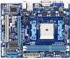
Bank Interleaving Enables or disables memory bank interleaving. Enabled allows the system to simultaneously access different banks of the memory to increase memory performance and stability. (Default: Enabled) ******** System Voltage Optimized System Voltage Control Determines whether to manually set the system voltages. Auto lets the BIOS automatically set the system voltages as required. Manual allows all voltage control items below to be configurable. (Default: Auto) DDR3 Voltage Control Allows you to set memory voltage. Normal Supplies the memory voltage as required. (Default) +0.1V ~+0.3V The adjustable range is from +0.1V to +0.3V. Note: Increasing memory voltage may result in damage to the memory or reduce the useful life of the memory. FCH Voltage Control Allows you to set the Chipset voltage. Normal Supplies the Chipset voltage as required. (Default) +0.1V ~+0.2V The adjustable range is from +0.1V to +0.2V. APU VDDP Voltage Control Allows you to set the APU PCIe PLL voltage. Normal Supplies the APU PCIe PLL voltage as required. (Default) +0.1V ~+0.2V The adjustable range is from +0.1V to +0.2V. Note: Increasing APU voltage may result in damage to your APU or reduce the useful life of the APU. CPU VCORE NB Control Allows you to set the CPU NorthBridge VID voltage. Normal Supplies the CPU NB VID voltage as required. (Default) -0.600V ~ +0.300V The adjustable range is from -0.600V to +0.300V. CPU VCORE Control Allows you to set the CPU voltage. Normal Supplies the CPU voltage as required. (Default) -0.600V ~ +0.400V The adjustable range is from -0.600V to +0.400V. Normal CPU Vcore Displays the normal operating voltage of your CPU. - 26 -
-
 1
1 -
2
-
3
-
4
-
5
-
6
-
7
-
8
-
9
-
10
-
11
-
12
-
13
-
14
-
15
-
16
-
17
-
18
-
19
-
20
-
 21
21 -
 22
22 -
 23
23 -
 24
24 -
 25
25 -
 26
26 -
 27
27 -
 28
28 -
 29
29 -
 30
30 -
 31
31 -
32
-
33
-
34
-
35
-
36
-
37
-
38
-
39
-
40
-
41
-
42
-
43
-
44
 |
 |
