Gigabyte GA-B75M-D3H Manual - Page 20
F_USB1/2 USB 2.0/1.1 Headers, from the power outlet to prevent damage to the USB bracket. - sata 3
 |
View all Gigabyte GA-B75M-D3H manuals
Add to My Manuals
Save this manual to your list of manuals |
Page 20 highlights
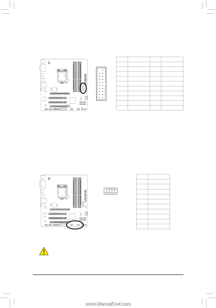
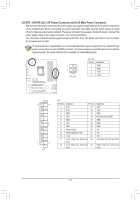
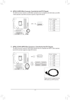
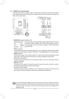
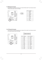
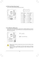
11) F_USB30 (USB 3.0/2.0 Header) The header cFo_UnSfoBr3m0 s to USB 3.0/2.0 specification and caFn_ApUrDoIvOid(He) two USB ports. For purchasing the optional 3.5" front panel that provides two USB 3.0/2.0 ports, please contact the local dealer. F_PANEL(NH) TPM w/housing Pin No. Definition Pin No. Definition 1 VBUS 11 D2+ 11 1 2 SSRX1- 3 SSRX1+ 12 D213 GND 4 GND 14 SSTX2+ 5 SSTX1D6B_PORTSSTX1+ 7 GND 20 10 8 D1- 15 SSTBXIO2S- Switcher (X58A-OC) 16 GND 17 SSRX2+1 18 SSRX2- M_SATA 9 D1+ 19 VBUS 10 NC 20 No Pin Voltage measurement module(X58A-OC) PWM Switch (X58A-OC) DIP 1 23 1 DIP 1 23 1 DIP 1 23 1 DIP 1 23 PCIe power connector (SATA)(X58A-OC) 12) F_USB1/2 (USB 2.0/1.1 Headers) The headers conform to USB 2.0/1.1 specification. Each USB header can provide two USB ports via an optional USB bracket. For purchasing the optional USB bracket, please contact the local dealer. 9 1 10 2 Pin No. 1 2 3 4 5 6 7 8 9 10 Definition Power (5V) Power (5V) USB DXUSB DYUSB DX+ USB DY+ GND GND No Pin NC •• Do not plug the IEEE 1394 bracket (2x5-pin) cable into the USB 2.0/1.1 header. •• Prior to installing the USB bracket, be sure to turn off your computer and unplug the power cord from the power outlet to prevent damage to the USB bracket. - 20 -
-
 1
1 -
2
-
3
-
4
-
5
-
6
-
7
-
8
-
9
-
10
-
11
-
12
-
13
-
14
-
 15
15 -
 16
16 -
 17
17 -
 18
18 -
 19
19 -
 20
20 -
 21
21 -
 22
22 -
 23
23 -
 24
24 -
 25
25 -
26
-
27
-
28
-
29
-
30
-
31
-
32
-
33
-
34
-
35
-
36
-
37
-
38
-
39
-
40
-
41
-
42
-
43
-
44
 |
 |