Gigabyte GA-GC220 Manual - Page 18
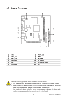
SATAII0/1 SATA 3Gb/s Connectors, Controlled by ICH7, PWR_LED System Power LED Header
 |
View all Gigabyte GA-GC220 manuals
Add to My Manuals
Save this manual to your list of manuals |
Page 18 highlights
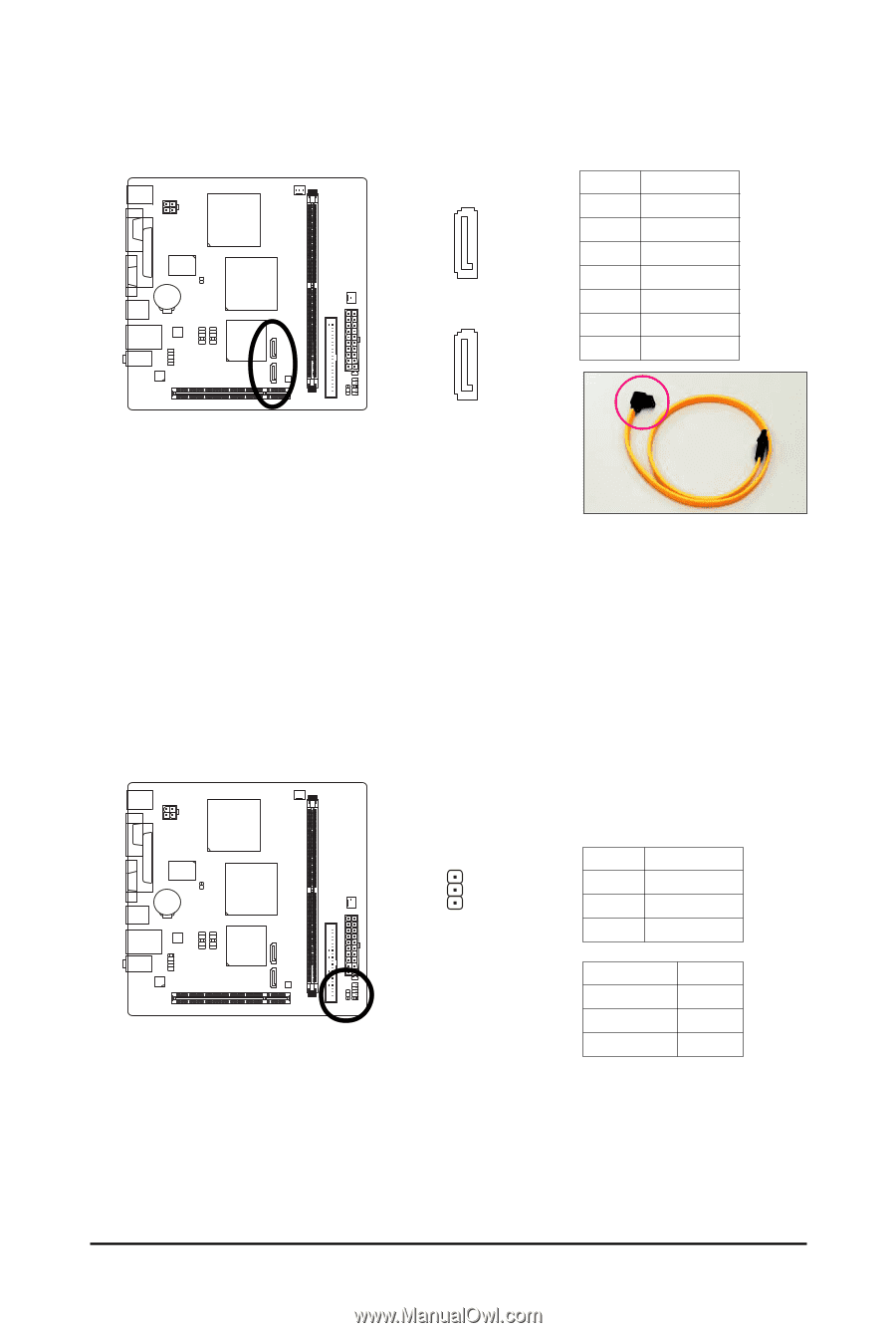
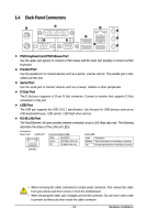
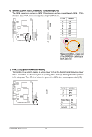
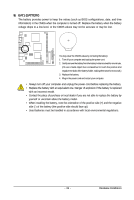
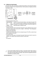
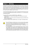
6) SATAII0/1 (SATA 3Gb/s Connectors, Controlled by ICH7) The SATA connectors conform to SATA 3Gb/s standard and are compatible with SATA 1.5Gb/s standard. Each SATA connector supports a single SATA device. Pin No. Definition 1 1 GND SATAII1 2 TXP 3 TXN 4 GND 7 5 RXN 1 6 RXP 7 GND SATAII0 7 Please connect the L-shaped end of the SATA 3Gb/s cable to your SATA hard drive. 7) PWR_LED (System Power LED Header) This header can be used to connect a system power LED on the chassis to indicate system power status. The LED is on when the system is operating. The LED keeps blinking when the system is in S1 sleep state. The LED is off when the system is in S3/S4 sleep state or powered off (S5). Pin No. Definition 1 MPD+ 2 MPD- 1 3 MPD- System Status LED S0 On S1 Blinking S3/S4/S5 Off GA-GC220 Motherboard - 18 -
-
 1
1 -
2
-
3
-
4
-
5
-
6
-
7
-
8
-
9
-
10
-
11
-
12
-
 13
13 -
 14
14 -
 15
15 -
 16
16 -
 17
17 -
 18
18 -
 19
19 -
 20
20 -
 21
21 -
 22
22 -
 23
23 -
24
-
25
-
26
-
27
-
28
-
29
-
30
-
31
-
32
-
33
-
34
-
35
-
36
-
37
-
38
-
39
-
40
-
41
-
42
-
43
-
44
-
45
-
46
-
47
-
48
-
49
-
50
-
51
-
52
-
53
-
54
-
55
-
56
-
57
-
58
-
59
-
60
-
61
-
62
-
63
-
64
-
65
-
66
-
67
-
68
-
69
-
70
-
71
-
72
 |
 |