Gigabyte GA-H55M-S2V Manual
Gigabyte GA-H55M-S2V Manual
 |
UPC - 818313011244
View all Gigabyte GA-H55M-S2V manuals
Add to My Manuals
Save this manual to your list of manuals |
Gigabyte GA-H55M-S2V manual content summary:
- Gigabyte GA-H55M-S2V | Manual - Page 1
GA-H55M-S2V GA-H55M-S2 LGA1156 socket motherboard for Intel® Core™ i7 processors/Intel® Core™ i5 processors/Intel® Core™ i3 processors/Intel® Pentium® processors User's Manual Rev. 1301 12ME-H55MS2V-1301R - Gigabyte GA-H55M-S2V | Manual - Page 2
Motherboard GA-H55M-S2V/GA-H55M-S2 Aug. 6, 2010 Motherboard GA-H55M-S2V GA-H55M-S2 Aug. 6, 2010 - Gigabyte GA-H55M-S2V | Manual - Page 3
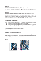
: For detailed product information, carefully read the User's Manual. For instructions on how to use GIGABYTE's unique features, read or download the information on/from the Support&Downloads\Motherboard\Technology Guide page on our website. For product-related information, check on - Gigabyte GA-H55M-S2V | Manual - Page 4
Layout 7 GA-H55M-S2V/GA-H55M-S2 Motherboard Block Diagram 8 Chapter 1 Hardware Installation 9 1-1 Installation Precautions 9 1-2 Product Specifications 10 1-3 Installing the CPU and CPU Cooler 12 1-3-1 Installing the CPU 12 1-3-2 Installing the CPU Cooler 14 1-4 Installing the Memory 15 - Gigabyte GA-H55M-S2V | Manual - Page 5
Installation 53 3-1 Installing Chipset Drivers 53 3-2 Application Software 54 3-3 Technical Manuals 54 3-4 Contact...55 3-5 System...55 3-6 Download Sound Recorder 72 5-2 Troubleshooting 73 5-2-1 Frequently Asked Questions 73 5-2-2 Troubleshooting Procedure 74 5-3 Regulatory Statements - Gigabyte GA-H55M-S2V | Manual - Page 6
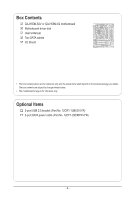
GA-H55M-S2V or GA-H55M-S2 motherboard Motherboard driver disk User's Manual Two SATA cables I/O Shield • The box contents above are for reference only and the actual items shall depend on the product package you obtain. The box contents are subject to change without notice. • The motherboard - Gigabyte GA-H55M-S2V | Manual - Page 7
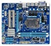
SATA2_2 SATA2_4 SATA2_1 SATA2_3 SATA2_0 GA-H55M-S2V/GA-H55M-S2 Motherboard Layout KB_MS ATX_12V Level Shifterj R_USB3 LGA1156 R_USB2 R_USB1 CPU_FAN USB_LAN AUDIO F_AUDIO PCIEX16 Realtek PCI1 RTL8111E PCI2 BAT GA-H55M-S2V GA-H55M-S2 Intel® H55 CODEC PCIEX1 SYS_FAN F_USB2 F_USB1 - Gigabyte GA-H55M-S2V | Manual - Page 8
GA-H55M-S2V/GA-H55M-S2 Motherboard Block Diagram 1 PCI Express x16 LGA1156 CPU CPU CLK+/- (133 MHz) DDR3 1666 (O.C.)/1333/1066/800 MHz Dual Channel Memory PCIe CLK (100 MHz) x16 PCI Express Bus 1 PCI Express x1 LAN PCIe CLK (100 MHz) PCI Express Bus x1 RJ45 Realtek RTL8111E x1 Intel® H55 - Gigabyte GA-H55M-S2V | Manual - Page 9
or memory. If you do not have an ESD wrist strap, keep your hands dry and first touch a metal object to eliminate static electricity. • Prior to installing the motherboard, please have it on top of an antistatic pad or within an electrostatic shielding container. • Before unplugging the power supply - Gigabyte GA-H55M-S2V | Manual - Page 10
Intel® Pentium® processors in the LGA1156 package (Go to GIGABYTE's website for the latest CPU support list.) L3 cache varies with CPU Chipset Intel® H55 Express Chipset Memory Onboard Graphics Audio 2 x 1.5V DDR3 DIMM sockets supporting up to 16 GB of - Gigabyte GA-H55M-S2V | Manual - Page 11
) Operating System w Support for Microsoft® Windows 7/Vista/XP Form Factor w Micro ATX Form Factor; 24.4cm x 21.0cm j Only for GA-H55M-S2V. (Note 1) Due to Windows 32-bit operating system limitation, when more than 4 GB of physical memory is installed, the actual memory size displayed will - Gigabyte GA-H55M-S2V | Manual - Page 12
before you begin to install the CPU: • Make sure that the motherboard supports the CPU. (Go to GIGABYTE's website for the latest CPU support list.) • Always turn off the computer and unplug the power cord from the power outlet before installing the CPU to prevent hardware damage. • Locate the - Gigabyte GA-H55M-S2V | Manual - Page 13
CPU into the motherboard CPU socket. Before installing the CPU, make sure to turn off the computer and unplug the power cord from the power outlet to prevent use one hand to hold the socket lever and use the other to lightly replace the load plate. When replacing the load plate, make sure the front - Gigabyte GA-H55M-S2V | Manual - Page 14
CPU cooler installation manual for instructions on installing the cooler.) Step 5: After the installation, check the back of the motherboard. If the push Step 6: Finally, attach the power connector of the CPU cooler to the CPU fan header (CPU_FAN) on the motherboard. Use extreme care when removing - Gigabyte GA-H55M-S2V | Manual - Page 15
that the motherboard supports the memory. It is recommended that memory of the same capacity, brand, speed, and chips be used. (Go to GIGABYTE's website for the latest supported memory speeds and memory modules.) • Always turn off the computer and unplug the power cord from the power outlet before - Gigabyte GA-H55M-S2V | Manual - Page 16
to turn off the computer and unplug the power cord from the power outlet to prevent damage to the memory module. DDR3 and DDR2 DIMMs are not compatible to each other or DDR DIMMs. Be sure to install DDR3 DIMMs on this motherboard. Notch DDR3 DIMM A DDR3 memory module has a notch, so it can only - Gigabyte GA-H55M-S2V | Manual - Page 17
motherboard supports the expansion card. Carefully read the manual that came with your expansion card. • Always turn off the computer and unplug the power cord from the power BIOS changes for your expansion card(s). 7. Install the driver provided with the expansion card in your operating system. - Gigabyte GA-H55M-S2V | Manual - Page 18
channel audio feature through the audio driver. Refer to the instructions on setting up a 2/4/5.1/7.1-channel motherboard. • When removing the cable, pull it straight out from the connector. Do not rock it side to side to prevent an electrical short inside the cable connector. Only for GA-H55M-S2V - Gigabyte GA-H55M-S2V | Manual - Page 19
with the connectors you wish to connect. • Before installing the devices, be sure to turn off the devices and your computer. Unplug the power cord from the power outlet to prevent damage to the devices. • After installing the device and before turning on the computer, make sure the device cable has - Gigabyte GA-H55M-S2V | Manual - Page 20
1/2) ATX_12V/ATX (2x2 12V Power Connector and 2x12 Main Power Connector) With the use of the power connector, the power supply can supply enough stable power to all the components on the motherboard. Before connecting the power connector, first make sure the power supply is turned off and all - Gigabyte GA-H55M-S2V | Manual - Page 21
correct orientation (the black connector wire is the ground wire). The motherboard supports CPU fan speed control, which requires the use of a CPU fan on the headers. 5) SATA2_0/1/2/3/4/5 (SATA 3Gb/s Connectors, Controlled by H55 Chipset) The SATA connectors conform to SATA 3Gb/s standard and are - Gigabyte GA-H55M-S2V | Manual - Page 22
may not be accurate or may be lost. You may clear the CMOS values by removing the battery: 1. Turn off your computer and unplug the power cord. 2. Gently remove the battery from the battery holder and wait for one minute. (Or use a metal object like a screwdriver to touch the positive and - Gigabyte GA-H55M-S2V | Manual - Page 23
problem. Refer to Chapter 5, "Troubleshooting," for information about beep codes. • HD (Hard Drive Activity LED, Blue) Connects to the hard drive activity LED on the chassis front panel. The LED module mainly consists of power switch, reset switch, power LED, hard drive activity LED, speaker and etc. - Gigabyte GA-H55M-S2V | Manual - Page 24
Power 4 -ACZ_DET 4 NC 5 LINE2_R 5 Line Out (R) 6 GND G.QBOFM 7 FAUDIO_JD 6 NC 7 NC 8 No Pin 8 No Pin 9 LINE2_L 9 Line Out (L) 10 GND 10 NC • The front panel audio header supports HD audio by default. If your chassis provides an AC'97 front panel audio module, refer to the instructions - Gigabyte GA-H55M-S2V | Manual - Page 25
CMOS Values • Always turn off your computer and unplug the power cord from the power outlet before clearing the CMOS values. • After clearing the CMOS to the motherboard. • After system restart, go to BIOS Setup to load factory defaults (select Load Optimized Defaults) or manually configure the - Gigabyte GA-H55M-S2V | Manual - Page 26
Hardware Installation - 26 - - Gigabyte GA-H55M-S2V | Manual - Page 27
that allows the user to modify basic system configuration settings or to activate certain system features. When the power is turned off, the battery on the motherboard supplies the necessary power to the CMOS to keep the configuration values in the CMOS. To access the BIOS Setup program, press - Gigabyte GA-H55M-S2V | Manual - Page 28
2-1 Startup Screen The following screens may appear when the computer boots. Motherboard Model BIOS Version Award Modular BIOS v6.00PG, An Energy Star Ally Copyright (C) 1984-2010, Award Software, Inc. H55M-S2V E1 . . . . : BIOS Setup : XpressRecovery2 : Boot Menu : Qflash 07/09 - Gigabyte GA-H55M-S2V | Manual - Page 29
> to accept or enter a sub-menu. (Sample BIOS Version: GA-H55M-S2V E1) CMOS Setup Utility-Copyright (C) 1984-2010 Award Software MB Intelligent Tweaker(M.I.T.) Standard CMOS Features Advanced BIOS Features Integrated Peripherals Power Management Setup PC Health Status ESC: Quit F8 - Gigabyte GA-H55M-S2V | Manual - Page 30
to complete. MB Intelligent Tweaker(M.I.T.) Use this menu to configure the clock, frequency and voltages of your CPU, memory, etc. Standard CMOS audio, and integrated LAN, etc. Power Management Setup Use this menu to configure all the power-saving functions. PC Health Status Use - Gigabyte GA-H55M-S2V | Manual - Page 31
BIOS Version BCLK CPU Frequency Memory Frequency Total Memory Size E1 133.27 MHz 3198.42 MHz 1332.80 MHz 1024 MB CPU Temperature PCH Temperature 45oC Defaults (Note) This item appears only if you install a memory module that supports this feature. - 31 - BIOS Setup - Gigabyte GA-H55M-S2V | Manual - Page 32
and voltage will be reduced during system halt state to decrease power consumption. Auto lets the BIOS automatically configure this setting. (Default: Auto) (Note) This item is present only if you install a CPU that supports this feature. For more information about Intel CPUs' unique features - Gigabyte GA-H55M-S2V | Manual - Page 33
Support (Note) Allows you to determine whether to let the CPU enter C3/C6/C7 mode in system halt state. When en- abled, the CPU core frequency and voltage will be reduced during system halt state to decrease power consumption. The C3/C6/C7 state is a more enhanced power you to manually set the - Gigabyte GA-H55M-S2V | Manual - Page 34
Memory Multiplier settings. Internal Graphics Clock Allows you to set the onboard graphics clock. The adjustable range is from 400 MHz to 2000 MHz. (Default: Auto) PCI Express Frequency(Mhz) Allows you to manually only if you install a memory module that supports this feature. BIOS Setup - 34 - - Gigabyte GA-H55M-S2V | Manual - Page 35
is set to Profile1 or Profile2, this item will display the value based on the SPD data on the XMP memory. Profile QPI Voltage The value displayed here is dependent on the CPU being used. (Note ) This item appears only if you install a memory module that supports this feature. - 35 - BIOS Setup - Gigabyte GA-H55M-S2V | Manual - Page 36
>>>>> Channel A/B Timing Settings CMOS Setup Utility-Copyright (C) 1984-2010 Award Software Channel A Timing Settings >>>>> Channel A Standard Timing Control x CAS Latency Time 9 x tRCD 9 x tRP 9 x tRAS 24 >>>>> Channel A Advanced Timing Control x tRC 33 x tRRD - Gigabyte GA-H55M-S2V | Manual - Page 37
tRTP Options are: Auto (default), 1~15. tFAW Options are: Auto (default), 1~63. Command Rate(CMD) Options are: Auto (default), 1~3. >>>>> Channel A/B Misc Timing Control Static tRD Options are: Auto (default), 1~31. Advanced Voltage Settings CMOS Setup Utility-Copyright (C) 1984-2010 Award - Gigabyte GA-H55M-S2V | Manual - Page 38
CPU Frequency Memory Frequency Total Memory Size E1 133.37 MHz 3067.78 MHz 1333.75 MHz 1024 MB CPU Temperature memory frequency, total memory size , CPU temperature, Chipset temperature, Vcore, and memory voltage. (Note) This item is present only if you install a CPU that supports - Gigabyte GA-H55M-S2V | Manual - Page 39
] [None] Halt On [All, But Keyboard] Base Memory Extended Memory Total Memory 640K 1022M 1024M Move Enter: Select F5: Previous Values device during the POST for faster system startup. Allows you to manually enter the specifications of the hard drive when the hard drive access - Gigabyte GA-H55M-S2V | Manual - Page 40
system boot will not stop for a keyboard error but stop for all other errors. (Default) Memory These fields are read-only and are determined by the BIOS POST. Base Memory Also called conventional memory. Typically, 640 KB will be reserved for the MS-DOS operating system. Extended - Gigabyte GA-H55M-S2V | Manual - Page 41
S.M.A.R.T. Capability Limit CPUID Max. to 3 (Note) No-Execute Memory Protect (Note) Delay For HDD (Secs) Backup BIOS Image to (Note) This item is present only if you install a CPU that supports this feature. For more information about Intel CPUs' unique features, please visit Intel's - Gigabyte GA-H55M-S2V | Manual - Page 42
graphics controller. MS-DOS, for example, will use only this memory for display. Options are: 32MB+2MB for GTT, 64MB+2MB for GTT (default), 128MB+2MB for GTT. (Note) This item is present only if you install a CPU that supports this feature. For more information about Intel CPUs' unique features - Gigabyte GA-H55M-S2V | Manual - Page 43
driver to enable advanced Serial ATA features such as Native Command Queuing and hot plug. SATA Port0-3 Native Mode (Intel H55 option to Disabled if you wish to install operating systems that do not support Native mode. Enabled Allows the SATA controllers to operate in Native IDE - Gigabyte GA-H55M-S2V | Manual - Page 44
No LAN Cable Is Attached... If no LAN cable is attached to the motherboard, the Status fields of all four pairs of wires will show Open and shown in the figure above. When LAN Cable Is Functioning Normally... If no cable problem is detected on the LAN cable connected to a Gigabit hub or a 10/100 - Gigabyte GA-H55M-S2V | Manual - Page 45
When a Cable Problem Occurs... If a cable problem occurs on a specified pair of wires, the Status field will show Short and then length shown will be the approximate distance to the fault or - Gigabyte GA-H55M-S2V | Manual - Page 46
, you need an ATX power supply providing at least 1A on the +5VSB lead. (Default: Enabled) Power On by Ring Allows the system to be awakened from an ACPI sleep state by a wake-up signal from a modem that supports wake-up function. (Default: Enabled) (Note) Supported on Windows 7/Vista operating - Gigabyte GA-H55M-S2V | Manual - Page 47
7/Vista. This item is configurable only if the HPET Support is set to Enabled. (Default: 32-bit mode) Power On By Mouse Allows the system to be turned on by a PS/2 mouse wake-up event. Note: To use this function, you need an ATX power supply providing at least 1A on the +5VSB lead - Gigabyte GA-H55M-S2V | Manual - Page 48
field will show "No" at next boot. (Default: Disabled) Case Opened Displays the detection status of the chassis intrusion detection device attached to the motherboard CI header. If the system chassis cover is removed, this field will show "Yes", otherwise it will show "No". To clear the chassis - Gigabyte GA-H55M-S2V | Manual - Page 49
CPU Smart FAN Mode Specifies how to control CPU fan speed. This item is configurable only if CPU Smart FAN Control is set to Enabled. Auto Lets the BIOS automatically detect the type of CPU fan installed and sets the optimal CPU fan control mode. (Default) Voltage Sets Voltage mode for a 3-pin - Gigabyte GA-H55M-S2V | Manual - Page 50
-Safe defaults, which are the safest and most stable BIOS settings for the motherboard. 2-10 Load Optimized Defaults CMOS Setup Utility-Copyright (C) 1984-2010 Award Software MB Intelligent Tweaker(M.I.T.) Load Fail-Safe Defaults Standard CMOS Features Load Optimized Defaults Advanced - Gigabyte GA-H55M-S2V | Manual - Page 51
2-11 Set Supervisor/User Password CMOS Setup Utility-Copyright (C) 1984-2010 Award Software MB Intelligent Tweaker(M.I.T.) Standard CMOS Features Advanced BIOS Features Integrated Peripherals Power Management SetupEnter Password: PC Health Status Load Fail-Safe Defaults Load Optimized - Gigabyte GA-H55M-S2V | Manual - Page 52
Saving CMOS Setup Utility-Copyright (C) 1984-2010 Award Software MB Intelligent Tweaker(M.I.T.) Load Fail-Safe Defaults Standard CMOS Features YSe/Nt S)?upNervisor Password Integrated Peripherals Set User Password Power Management Setup Save & Exit Setup PC Health Status Exit - Gigabyte GA-H55M-S2V | Manual - Page 53
install new GIGABYTE utilities. Click Yes to automatically install the utilities. Or click No if you want to manually select the utilities to install on the Application Software page later. • For USB 2.0 driver support under the Windows XP operating system, please install the Windows XP Service Pack - Gigabyte GA-H55M-S2V | Manual - Page 54
applications that GIGABYTE develops and some free software. You can click the Install button on the right of an item to install it. 3-3 Technical Manuals This page provides GIGABYTE's application guides, content descriptions for this driver disk, and the motherboard manuals. Drivers Installation - Gigabyte GA-H55M-S2V | Manual - Page 55
3-4 Contact For the detailed contact information of the GIGABYTE Taiwan headquarter or worldwide branch offices, click the URL on this page to link to the GIGABYTE website. 3-5 System This page provides the basic system information. - 55 - Drivers Installation - Gigabyte GA-H55M-S2V | Manual - Page 56
, or applications, click the Download Center button to link to the GIGABYTE website. The latest version of the BIOS, drivers, or applications will be displayed. 3-7 New Utilities This page provides a quick link to GIGABYTE's lately developed utilities for users to install. You can click the Install - Gigabyte GA-H55M-S2V | Manual - Page 57
up your system soon after the operating system and drivers are installed. • The amount of data and hard drive it. System Requirements: • At least 512 MB of system memory • VESA compatible graphics card • Windows XP are not supported. • Hard drives in RAID/AHCI mode are not supported. Installation and - Gigabyte GA-H55M-S2V | Manual - Page 58
note that if there is no enough unallocated space, Xpress Recovery2 cannot save the backup file. B. Accessing Xpress Recovery2 1. Boot from the motherboard driver disk to access Xpress Recovery2 for the first time. When you see the following message: Press any key to startup Xpress Recovery2, press - Gigabyte GA-H55M-S2V | Manual - Page 59
D. Using the Restore Function in Xpress Recovery2 Select RESTORE to restore the backup to your hard drive in case the system breaks down. The RESTORE option will not be present if no backup is created before. E. Removing the Backup Step 1: If you wish to remove the backup file, select REMOVE. Step - Gigabyte GA-H55M-S2V | Manual - Page 60
Motherboards that support DualBIOS backup BIOS manually. What GIGABYTE's website, download the latest compressed BIOS update file that matches your motherboard a hard drive in RAID/AHCI mode or a H55M-S2V E1 . . . . : BIOS Setup : XpressRecovery2 : Boot Menu : Qflash 07/09/2010-H55 - Gigabyte GA-H55M-S2V | Manual - Page 61
current BIOS file. • Q-Flash only supports USB flash drive or hard drives using FAT32/16/12 update file is saved to a hard drive in RAID/AHCI mode or a hard drive attached to an :Power Off 3. Select the BIOS update file and press . Make sure the BIOS update file matches your motherboard - Gigabyte GA-H55M-S2V | Manual - Page 62
that you reload BIOS defaults. CMOS Setup Utility-Copyright (C) 1984-2010 Award Software MB Intelligent Tweaker(M.I.T.) Standard CMOS Features Advanced BIOS Features Integrated Peripherals Power Management Setup PC Health Status ESC: Quit F8: Q-Flash Load Fail-Safe Defaults - Gigabyte GA-H55M-S2V | Manual - Page 63
stable and do NOT interrupt the Internet connection (for example, avoid a power loss or switching off the Internet). Failure to do so may result in motherboard is not present on the @BIOS server site, please manually download the BIOS update file from GIGABYTE's website and follow the instructions - Gigabyte GA-H55M-S2V | Manual - Page 64
(.wav file). (Note) Due to the hardware limitation, you must install a DDR3 1066 MHz memory module(s) (or above) to enable support for Quick Boost. Available functions in EasyTune 6 may differ by motherboard model. Grayed-out area(s) indicates that the item is not configurable or the function is - Gigabyte GA-H55M-S2V | Manual - Page 65
on the same network, making full use of Internet resources. Directions for using Q-Share After installing Q-Share from the motherboard driver disk, go to Start>All Programs>GIGABYTE>Q-Share. exe to launch the Q-Share tool. Find the Q-Share icon to configure the data sharing settings. in the - Gigabyte GA-H55M-S2V | Manual - Page 66
main menu and click Save to save the settings. Button Standby Suspend Disable Description Enters Power on Suspend mode Enters Suspend to RAM mode Disables this function The Bluetooth dongle included in the motherboard package(Note 2) allows you to wake up the system from Suspend to RAM mode - Gigabyte GA-H55M-S2V | Manual - Page 67
jack and manually configure the jack for microphone functionality. • Audio signals will be present on both of the front and back panel audio connections simultaneously. If you want to mute the back panel audio (only supported when using an HD front panel audio module), refer to instructions on the - Gigabyte GA-H55M-S2V | Manual - Page 68
The pictures to the right show the 7.1-channel speaker configurations. 7.1-Channel Speakers: Front Speaker Out Rear Speaker Out Center/Subwoofer Speaker Out Step 2: Connect an audio device to an audio jack. The The current connected device is dialog box appears. Select the device according to the - Gigabyte GA-H55M-S2V | Manual - Page 69
C. Activating an AC'97 Front Panel Audio Module If your chassis provides an AC'97 front panel audio module, to activate the AC'97 functionality, click the tool icon on the Speaker Configuration tab. On the Connector Settings dialog box, select the Disable front panel jack detection check box. Click - Gigabyte GA-H55M-S2V | Manual - Page 70
5-1-2 Configuring Microphone Recording Step 1: After installing the audio driver, the HD Audio Manager icon will appear in the notification area. Double-click the icon to access the HD Audio Manager. Step 2: Connect your microphone - Gigabyte GA-H55M-S2V | Manual - Page 71
Step 4: To raise the recording and playback volume for the microphone, click the Microphone Boost icon on the right of the Recording Volume slider and set the Microphone Boost level. Step 5: After completing the settings above, click Start, point to All Programs, point to Accessories, and then click - Gigabyte GA-H55M-S2V | Manual - Page 72
. Be sure to save the recorded audio file upon completion. B. Playing the Recorded Sound You can play your recording in a digital media player program that supports your audio file format. Appendix - 72 - - Gigabyte GA-H55M-S2V | Manual - Page 73
New Hardware Wizard appears, click Cancel. Then install the onboard HD audio driver from the motherboard driver disk or download the audio driver from GIGABYTE's website to install. For more details, go to the Support&Downloads\Motherboards\FAQ page on our website and search for "onboard HD audio - Gigabyte GA-H55M-S2V | Manual - Page 74
Procedure If you encounter any troubles during system startup, follow the troubleshooting procedure below to solve the problem. START Turn off the power. Remove all peripherals, connecting cables, and power cord etc. Make sure the motherboard does not short-circuit with the chassis or - Gigabyte GA-H55M-S2V | Manual - Page 75
is turned on, is the CPU cooler running? No The power supply, CPU or CPU socket might fail. Yes Check if there is display on your monitor. Yes Turn off the computer. Plug in the keyboard and mouse and restart the computer. The problem is verified and solved. No The graphics card, expansion - Gigabyte GA-H55M-S2V | Manual - Page 76
GIGABYTE. Our Commitment to Preserving the Environment In addition to high-efficiency performance, all GIGABYTE motherboards local government office, your household waste disposal service or where you purchased the product for user's manual and we will be glad to help you with your effort. Appendix - Gigabyte GA-H55M-S2V | Manual - Page 77
that potentially hazardous substances are not released into the environment and are disposed of properly. China Restriction of Hazardous Substances Table The following table is supplied in compliance with China's Restriction of Hazardous Substances (China RoHS) requirements: - 77 - Appendix - Gigabyte GA-H55M-S2V | Manual - Page 78
Appendix - 78 - - Gigabyte GA-H55M-S2V | Manual - Page 79
Shenyang TEL: +86-24-83992901 FAX: +86-24-83992909 • GIGABYTE TECHNOLOGY (INDIA) LIMITED - India WEB address : http://www.gigabyte.in • Saudi Arabia WEB address : http://www.gigabyte.com.sa • Gigabyte Technology Pty. Ltd. - Australia WEB address : http://www.gigabyte.com.au - 79 - Appendix - Gigabyte GA-H55M-S2V | Manual - Page 80
website, select your language in the language list on the top right corner of the website. • GIGABYTE Global Service System To submit a technical or non-technical (Sales/Marketing) question, please link to: http://ggts.gigabyte.com.tw Then select your language to enter the system. Appendix - 80 -
-
 1
1 -
 2
2 -
 3
3 -
 4
4 -
 5
5 -
 6
6 -
 7
7 -
8
-
9
-
10
-
11
-
12
-
13
-
14
-
15
-
16
-
17
-
18
-
19
-
20
-
21
-
22
-
23
-
24
-
25
-
26
-
27
-
28
-
29
-
30
-
31
-
32
-
33
-
34
-
35
-
36
-
37
-
38
-
39
-
40
-
41
-
42
-
43
-
44
-
45
-
46
-
47
-
48
-
49
-
50
-
51
-
52
-
53
-
54
-
55
-
56
-
57
-
58
-
59
-
60
-
61
-
62
-
63
-
64
-
65
-
66
-
67
-
68
-
69
-
70
-
71
-
72
-
73
-
74
-
75
-
76
-
77
-
78
-
79
-
80
 |
 |

GA-H55M-S2V
GA-H55M-S2
LGA1156 socket motherboard for Intel
®
Core
™
i7 processors/Intel
®
Core
™
i5 processors/Intel
®
Core
™
i3 processors/Intel
®
Pentium
®
processors
User's Manual
Rev. 1301
12ME-H55MS2V-1301R