Gigabyte GA-H55M-S2V Manual - Page 18
Back Panel Connectors, PS/2 Keyboard and PS/2 Mouse Port, D-Sub Port, DVI-D Port, USB 2.0/1.1 - lan driver
 |
UPC - 818313011244
View all Gigabyte GA-H55M-S2V manuals
Add to My Manuals
Save this manual to your list of manuals |
Page 18 highlights
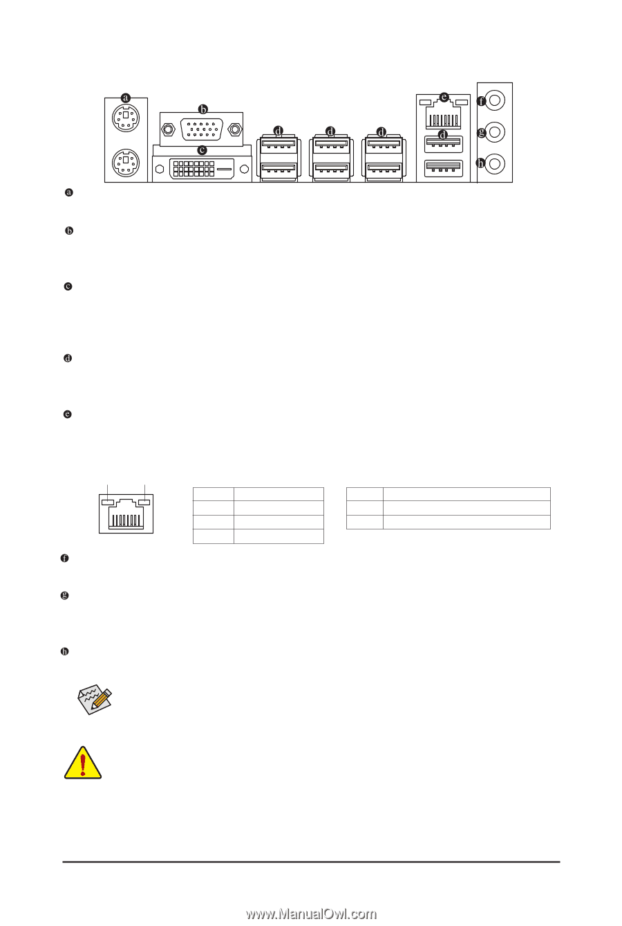
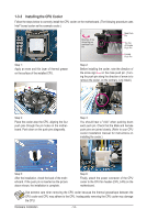
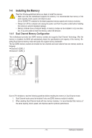
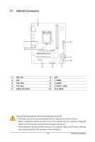
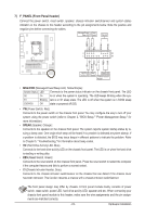
1-6 Back Panel Connectors j PS/2 Keyboard and PS/2 Mouse Port Use the upper port (green) to connect a PS/2 mouse and the lower port (purple) to connect a PS/2 keyboard. D-Sub Port (Note 1) The D-Sub port supports a 15-pin D-Sub connector. Connect a monitor that supports D-Sub connection to this port. DVI-D Port j (Note 2) The DVI-D port conforms to the DVI-D specification and supports a maximum resolution of 1920x1200 (the actual resolutions supported depend on the monitor being used). Connect a monitor that supports DVI-D connection to this port. USB 2.0/1.1 The USB port supports the USB 2.0/1.1 specification. Use this port for USB devices such as a USB key board/mouse, USB printer, USB flash drive and etc. RJ-45 LAN Port The Gigabit Ethernet LAN port provides Internet connection at up to 1 Gbps data rate. The following describes the states of the LAN port LEDs. Connection/ Speed LED Activity LED LAN Port Line In Jack (Blue) Connection/Speed LED: State Description Orange 1 Gbps data rate Green 100 Mbps data rate Off 10 Mbps data rate Activity LED: State Description Blinking Data transmission or receiving is occurring Off No data transmission or receiving is occurring The default line in jack. Use this audio jack for line in devices such as an optical drive, walkman, etc. Line Out Jack (Green) The default line out jack. Use this audio jack for a headphone or 2-channel speaker. This jack can be used to connect front speakers in a 4/5.1/7.1-channel audio configuration. Mic In Jack (Pink) The default Mic in jack. Microphones must be connected to this jack. To configure 7.1-channel audio, you have to use an HD front panel audio module and enable the multi-channel audio feature through the audio driver. Refer to the instructions on setting up a 2/4/5.1/7.1-channel audio configuration in Chapter 5, "Configuring 2/4/5.1/7.1-Channel Audio." j • When removing the cable connected to a back panel connector, first remove the cable from your device and then remove it from the motherboard. • When removing the cable, pull it straight out from the connector. Do not rock it side to side to prevent an electrical short inside the cable connector. Only for GA-H55M-S2V (Note 1) To use the onboard DVI-D/D-Sub port, you must install an Intel CPU with integrated graphics. (Note 2) The DVI-D port does not support D-Sub connection by adapter. Hardware Installation - 18 -
-
 1
1 -
2
-
3
-
4
-
5
-
6
-
7
-
8
-
9
-
10
-
11
-
12
-
 13
13 -
 14
14 -
 15
15 -
 16
16 -
 17
17 -
 18
18 -
 19
19 -
 20
20 -
 21
21 -
 22
22 -
 23
23 -
24
-
25
-
26
-
27
-
28
-
29
-
30
-
31
-
32
-
33
-
34
-
35
-
36
-
37
-
38
-
39
-
40
-
41
-
42
-
43
-
44
-
45
-
46
-
47
-
48
-
49
-
50
-
51
-
52
-
53
-
54
-
55
-
56
-
57
-
58
-
59
-
60
-
61
-
62
-
63
-
64
-
65
-
66
-
67
-
68
-
69
-
70
-
71
-
72
-
73
-
74
-
75
-
76
-
77
-
78
-
79
-
80
 |
 |