Gigabyte GA-H61N-USB3 Manual - Page 24
F_PANEL Front Panel Header, Hard Drive Activity LED, Blue
 |
View all Gigabyte GA-H61N-USB3 manuals
Add to My Manuals
Save this manual to your list of manuals |
Page 24 highlights
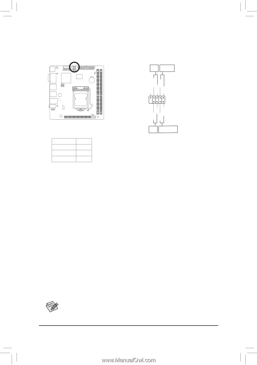
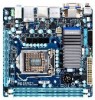
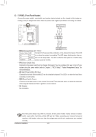
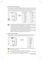
6) F_PANEL (Front Panel Header) Connect the power switch, reset switch, and system status indicator on the chassis to this header according to the pin assignments below. Note the positive and negative pins before connecting the cables. Reset Hard Drive Switch Activity LED NC RES+ RESHD- HD+ 9 1 10 2 PWPW+ MSGMSG+ •• MSG (Message/Sleep LED, Yellow): Power Message/Sleep Switch LED System Status LED Connects to the power status indicator on the chassis front panel. The LED S0 On is on when the system is operating. The LED keeps blinking when the sys- S1 Blinking tem is in S1 sleep state. The LED is off when the system is in S3/S4 sleep S3/S4/S5 Off state or powered off (S5). •• PW (Power Switch, Red): Connects to the power switch on the chassis front panel. You may configure the way to turn off your system using the power switch (refer to Chapter 2, "BIOS Setup," "Power Management Setup," for more information). •• HD (Hard Drive Activity LED, Blue) Connects to the hard drive activity LED on the chassis front panel. The LED is on when the hard drive is reading or writing data. •• RES (Reset Switch, Green): Connects to the reset switch on the chassis front panel. Press the reset switch to restart the computer if the computer freezes and fails to perform a normal restart. •• NC (Purple): No connection. The front panel design may differ by chassis. A front panel module mainly consists of power switch, reset switch, hard drive activity LED and etc. When connecting your chassis front panel module to this header, make sure the wire assignments and the pin assignments are matched correctly. Hardware Installation - 24 -
-
 1
1 -
2
-
3
-
4
-
5
-
6
-
7
-
8
-
9
-
10
-
11
-
12
-
13
-
14
-
15
-
16
-
17
-
18
-
 19
19 -
 20
20 -
 21
21 -
 22
22 -
 23
23 -
 24
24 -
 25
25 -
 26
26 -
 27
27 -
 28
28 -
 29
29 -
30
-
31
-
32
-
33
-
34
-
35
-
36
-
37
-
38
-
39
-
40
-
41
-
42
-
43
-
44
-
45
-
46
-
47
-
48
-
49
-
50
-
51
-
52
-
53
-
54
-
55
-
56
-
57
-
58
-
59
-
60
-
61
-
62
-
63
-
64
-
65
-
66
-
67
-
68
-
69
-
70
-
71
-
72
-
73
-
74
-
75
-
76
-
77
-
78
-
79
-
80
-
81
-
82
-
83
-
84
-
85
-
86
-
87
-
88
 |
 |