Gigabyte GA-K8NF-9 User Manual
Gigabyte GA-K8NF-9 Manual
 |
View all Gigabyte GA-K8NF-9 manuals
Add to My Manuals
Save this manual to your list of manuals |
Gigabyte GA-K8NF-9 manual content summary:
- Gigabyte GA-K8NF-9 | User Manual - Page 1
GA-K8NF-9 AMD Socket 939 Processor Motherboard User's Manual Rev. 1005 12ME-K8NF9-1005 - Gigabyte GA-K8NF-9 | User Manual - Page 2
Motherboard GA-K8NF-9 Dec. 24, 2004 Motherboard GA-K8NF-9 Dec. 24, 2004 - Gigabyte GA-K8NF-9 | User Manual - Page 3
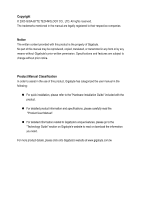
product. „ For detailed product information and specifications, please carefully read the "Product User Manual". „ For detailed information related to Gigabyte's unique features, please go to the "Technology Guide" section on Gigabyte's website to read or download the information you need. For more - Gigabyte GA-K8NF-9 | User Manual - Page 4
Table of Contents GA-K8NF-9 Motherboard Layout 6 Block Diagram ...7 Chapter 1 Hardware Installation 9 1-1 Considerations Prior to Installation 9 1-2 Feature Summary 10 1-3 Installation of the CPU and Fan Heat Sink 12 1-3-1 Installation of the CPU 12 1-3-2 Installation of the Fan Heat Sink 13 - Gigabyte GA-K8NF-9 | User Manual - Page 5
Chapter 3 Drivers Installation 47 3-1 Install Chipset Drivers 47 3-2 SoftwareApplication 48 3-3 Software Information 48 3-4 Flash BIOS Method Introduction 54 4-1-4 Serial ATA BIOS Setting Utility Introduction 63 4-1-5 2- / 4- / 6- / 8- Channel Audio Function Introduction 69 4-2 Troubleshooting - Gigabyte GA-K8NF-9 | User Manual - Page 6
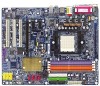
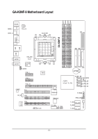
GA-K8NF-9 DDR1 DDR2 DDR3 DDR4 GA-K8NF-9 Motherboard Layout KB_MS SPDIF_I ATX_12V ATX SPDIF_O Socket 939 COMA LPT LAN USB IDE2 IDE1 USB IT8712 SYS_FAN AUDIO1 CPU_FAN AUDIO2 VITESSE 8201 F_AUDIO PCIE_1 BIOS PCIE_2 PCIE_16 CODEC PCI1 CD_IN PCI2 PCI3 IR_CIR FDD BATTERY - Gigabyte GA-K8NF-9 | User Manual - Page 7
Diagram PCI-ECLK (100MHz) PCI Express x 16 AMD K8 Socket 939 CPU CPUCLK+/-(200MHz) DDR 400/333/266/200MHz DIMM Dual Channel Memory Hyper Transport Bus 2 PCI Express x 1 Ports PCI-ECLK (100MHz) RJ45 VITESSE 8201 nVIDIA® nForce4(-4X) BIOS 4 Serial ATA ATA33/66/100/133 IDE Channels PCI - Gigabyte GA-K8NF-9 | User Manual - Page 8
- 8 - - Gigabyte GA-K8NF-9 | User Manual - Page 9
instructions below: 1. Please turn off the computer and unplug its power cord. 2. When handling the motherboard, avoid touching any metal leads or connectors. 3. It is best to wear an electrostatic discharge (ESD) cuff when handling electronic components (CPU, RAM motherboard a problem related manual. - Gigabyte GA-K8NF-9 | User Manual - Page 10
Memory Slots IDE Connections FDD Connections Onboard SATA Peripherals Onboard LAN Onboard Audio Š Socket 939 for AMD SempronTM / AlthlonTM 64 / AlthlonTM 64 FX / AlthlonTM 64 X2 Dual-Core processor (K8) Š 1600MHz system bus Š Supports core frequencies in excess of 3000+ and faster Š nVIDIA® nForce4 - Gigabyte GA-K8NF-9 | User Manual - Page 11
(RAID 0+1) - supports data transfer rate of up to 150 MB/s - supports hot plugging function - supports a maximum of 4 SATA connections Supported on the Win 2000/XP operating systems Use of licensed AWARD BIOS Supports Q-Flash Supports @BIOS Supports EasyTune (Note 2) Over Voltage via BIOS (CPU - Gigabyte GA-K8NF-9 | User Manual - Page 12
to your hardware specifications including the CPU, graphics card, memory, hard drive, etc. 1-3-1 Installation of the CPU Check the processor pins to see that none are bent. Move the socket lever to the unlocked position as shown in Figure 1.(90o to the plane of the motherboard) prior to inserting - Gigabyte GA-K8NF-9 | User Manual - Page 13
sink paste on the surface of the CPU. Install all the heat sink components (Please refer to the heat sink manual for detailed installation instructions). Fig.2 Please connect the heat sink power connector to the CPU_FAN connector located on the motherboard so that the heat sink can properly function - Gigabyte GA-K8NF-9 | User Manual - Page 14
in only one direction. If you are unable to insert the module, please switch the direction. The motherboard supports DDR memory modules, whereby BIOS will automatically detect memory capacity and specifications. Memory modules are designed so that they can be inserted only in one direction. The - Gigabyte GA-K8NF-9 | User Manual - Page 15
English Dual Channel DDR GA-K8NF-9 supports the Dual Channel Technology. After operating the Dual Channel Technology, the bandwidth of Memory Bus will double. GA-K8NF-9 includes 4 DIMM sockets, and each Channel has two DIMM sockets as following: Channel A : DDR 1, DDR 3 Channel B : DDR 2, DDR 4 If - Gigabyte GA-K8NF-9 | User Manual - Page 16
bar at the end of the PCI Express x 16 slot when you try to install/uninstall the VGA card. Please align the VGA card to the onboard PCI Express x 16 slot and press firmly down on the slot. Make sure your VGA card is locked by the small white-drawable bar. GA-K8NF-9 Motherboard - 16 - - Gigabyte GA-K8NF-9 | User Manual - Page 17
SPDIF_O (SPDIF Out) The SPDIF output is capable of providing digital audio to external speakers or compressed AC3 data to an external Dolby Digital sure your OS supports USB controller. If your OS does not support USB controller, please contact OS vendor for possible patch or driver upgrade. For - Gigabyte GA-K8NF-9 | User Manual - Page 18
Connect the side surround speakers to this connector. You can use audio software to configure 2-/4-/6-/8-channel audio functioning. 1-7 Connectors Introduction 13 6 2 10 11 14 1) 12) F_USB1 / F_USB2 / F_USB3 13) F1_1394 / F2_1394 14) IR_CIR 15) CLR_CMOS 16) BATTERY GA-K8NF-9 Motherboard - 18 - - Gigabyte GA-K8NF-9 | User Manual - Page 19
properly installed. Align the power connector with its proper location on the motherboard and connect tightly. The ATX_12V power connector mainly supplies power to the CPU. If the ATX_12V power connector is not connected, the system will not start. Caution! Please use a power supply that is able to - Gigabyte GA-K8NF-9 | User Manual - Page 20
a foolproof connection design. Most coolers are designed with color-coded power connector wires. A red power connector wire indicates a positive to the CPU fan to prevent CPU overheating and failure. 1 CPU_FAN 1 Pin No. 1 2 3 Definition GND +12V Sense SYS_FAN GA-K8NF-9 Motherboard - 20 - Gigabyte GA-K8NF-9 | User Manual - Page 21
cable while the other end of the cable connects to the FDD drive. The types of FDD drives supported are: 360KB, 720KB, 1.2MB, 1.44MB and 2.88MB. Please connect the red power connector wire to refer to the instructions located on the IDE device). 40 39 2 IDE2 1 IDE1 - 21 - Hardware Installation - Gigabyte GA-K8NF-9 | User Manual - Page 22
nForce4(-4X)) Serial ATA can provide up to 150MB/s transfer rate. Please refer to the BIOS setting for the Serial ATA and install the proper driver the system is on/off. It will blink when the system enters suspend mode. Pin No. Definition 1 MPD+ 2 MPD- 1 3 MPD- GA-K8NF-9 Motherboard - 22 - - Gigabyte GA-K8NF-9 | User Manual - Page 23
Switch IDE Hard Disk Active LED SPEAK (Speaker Connector) (Amber) PW (Power Switch) (Red) MSG (Message LED/Power/Sleep LED) (Yellow) RES (Reset Switch) (Green) HD (IDE Hard Disk Active LED) (Blue) NC (Purple) Pin 1: VCC(+) Pin 2- Pin 3: NC Pin 4: Data(-) Open: Normal Operation Close: Power On - Gigabyte GA-K8NF-9 | User Manual - Page 24
7 8 9 10 Definition MIC GND MIC_BIAS Power Front Audio(R) Rear Audio(R)/Return R NC No Pin Front Audio(L) Rear Audio(L)/Return L 11) CD_IN (CD In Connector) Connect CD-ROM or DVD-ROM audio out to the connector. Pin No. Definition 1 1 CD-L 2 GND 3 GND 4 CD-R GA-K8NF-9 Motherboard - 24 - - Gigabyte GA-K8NF-9 | User Manual - Page 25
you connect the front USB cable, incorrect connection between the cable and connector will make the device unable to work or even damage it. For optional front the IEEE1394 cable, incorrect connection between the cable and connector will make the device unable to work or even damage it. For - Gigabyte GA-K8NF-9 | User Manual - Page 26
assignment carefully while you connect the IR/CIR cable, incorrect connection between the cable and connector will make the device unable to work or even damage it. For optional IR/CIR cable, please contact from improper use this jumper. Open: Normal 1 Short: Clear CMOS 1 GA-K8NF-9 Motherboard - 26 - - Gigabyte GA-K8NF-9 | User Manual - Page 27
is incorrectly replaced. Replace only with the same or equivalent type recommended by the manufacturer. Dispose of used batteries according to the manufacturer's instructions. If you want to erase CMOS... 1. Turn off the computer and unplug the power cord. 2. Take out the battery gently and put it - Gigabyte GA-K8NF-9 | User Manual - Page 28
English GA-K8NF-9 Motherboard - 28 - - Gigabyte GA-K8NF-9 | User Manual - Page 29
BIOS, either GIGABYTE's Q-Flash or @BIOS utility can be used. Q-Flash allows the user to quickly and easily update or backup BIOS without entering the operating system. @BIOS is a Windows-based utility that does not require users to boot to DOS before upgrading BIOS but directly download and update - Gigabyte GA-K8NF-9 | User Manual - Page 30
Defaults in the BIOS when somehow the system works not stable as usual. This action makes the system reset to the default for stability. The BIOS Setup menus described in this chapter are for reference only and may differ from the exact settings for your motherboard. GA-K8NF-9 Motherboard - 30 - - Gigabyte GA-K8NF-9 | User Manual - Page 31
setup page includes all the items in standard compatible BIOS. „ Advanced BIOS Features This setup page includes all the items of voltage, fan, speed. „ MB Intelligent Tweaker(M.I.T.) This setup page is control CPU clock and frequency ratio. „ Top Performance If you wish to maximize the performance - Gigabyte GA-K8NF-9 | User Manual - Page 32
Values F10: Save ESC: Exit F7: Optimized Defaults F1: General Help BIOS to automatically detect IDE devices during POST(default) • None Select this if no IDE devices are used and the system will skip the automatic detection step and allow for faster system start up. GA-K8NF-9 Motherboard - Gigabyte GA-K8NF-9 | User Manual - Page 33
. (Default value) All, But Diskette The system boot will not stop for a disk error; it will stop for all other errors. All, But Disk/Key The system boot will not stop for a keyboard or disk error; it will stop for all other errors. Floppy 3 Mode Support (for Japan Area) Disabled Drive A Normal - Gigabyte GA-K8NF-9 | User Manual - Page 34
KLJI: Move Enter: Select +/-/PU/PD: Value F5: Previous Values F10: Save ESC: Exit F7: Optimized Defaults F1: General Help Hard Disk Boot Priority Select boot sequence for onboard(or add-on cards) SCSI, RAID, etc. Use < > or < > to select a device, then press to move it up, or to - Gigabyte GA-K8NF-9 | User Manual - Page 35
LAN BOOT ROM NV IDE/SATA RAID function x IDE Primary Master RAID x IDE Primary Slave RAID x IDE Secndry Master RAID x IDE Secndry Slave RAID NV Serial-ATA 1 x NV SATA 1 class code x NV SATA 1 Primary RAID x NV SATA 1 Secondary RAID NV Serial-ATA 2 x NV SATA 2 class code x NV SATA 2 Primary RAID x NV - Gigabyte GA-K8NF-9 | User Manual - Page 36
function. (Default value) NV Serial-ATA 2 Enabled Enable Serial ATA 2 supported. (Default value) Disabled Disable Serial ATA 2 supported. NV SATA 2 class code (Note) 0101 Set NV SATA 2 class code to 0101. (Default value) 0104 Set NV SATA 2 class code to 0104. GA-K8NF-9 Motherboard - 36 - - Gigabyte GA-K8NF-9 | User Manual - Page 37
and address is 3BC/IRQ7. (Note) When using driver version 1.2, please enable "NV IDE/SATA RAID function" if you wish to create RAID data drive or install O.S. on the RAID drive. And manually set "NV SATA1/NV SATA 2 class code" from 0101 to 0104. If your SATA hard drive is connected to the SATA0 or - Gigabyte GA-K8NF-9 | User Manual - Page 38
Default value) Legacy (DOS) USB Mouse Enabled Disabled Enable USB mouse support in the MS-DOS environment. Disable this function. (Default value) Legacy USB storage detect Enabled Disabled Enable USB storage detect function. (Default value) Disable this function. GA-K8NF-9 Motherboard - 38 - - Gigabyte GA-K8NF-9 | User Manual - Page 39
+/-/PU/PD: Value F5: Previous Values F10: Save ESC: Exit F7: Optimized Defaults F1: General Help ACPI Suspend Type S1(POS) Set value) S3(STR) Set ACPI suspend type to S3/STR(Suspend To RAM). Soft-Off by Power button Instant-off Press power button then Power : (0~59) - 39 - BIOS Setup - Gigabyte GA-K8NF-9 | User Manual - Page 40
Function Soft-Off When AC-power back to the system, the system will be in "Off" state. (Default value) Full-On When AC- +/-/PU/PD: Value F5: Previous Values F10: Save ESC: Exit F7: Optimized Defaults F1: General Help PCI 1 IRQ Assignment Auto 3,4,5,7,9,10, GA-K8NF-9 Motherboard - 40 - - Gigabyte GA-K8NF-9 | User Manual - Page 41
Exit F7: CPU fan runs at full speed when both CPU Smart FAN Control and CPU FAN Manual Control are disabled. Whether the CPU Smart FAN Control function is supported will depend on the CPU you install. For more detailed information please check at the FAQ section on GIGABYTE's website. - 41 - BIOS - Gigabyte GA-K8NF-9 | User Manual - Page 42
in CPU FAN: High Speed. For example, by default, when the CPU temperature exceeds 60oC, CPU fan runs with parameter 80. Temp of full FAN Speed (Default temperature: 70oC) When the CPU temperature exceeds the value set in this option, the CPU fan runs at full speed. GA-K8NF-9 Motherboard - 42 - Gigabyte GA-K8NF-9 | User Manual - Page 43
options can enhance the VGA graphics card bandwidth to get higher performance. Auto Set Robust Graphics Booster to Auto. (Default value) Fast Turbo Set Robust Graphics Booster to Fast. Set Robust Graphics Booster to Turbo. CPU Voltage Control Supports adjustable CPU Vcore from 0.800V to 1.750V - Gigabyte GA-K8NF-9 | User Manual - Page 44
BIOS F8: Q-Flash KLJI: Select Windows XP, but works smoothly with Windows NT. Therefore, if your system is not perform enough, the reliability or stability problem will appear sometimes, and we will recommend you disabling the option to avoid the problem as mentioned above. GA-K8NF-9 Motherboard - Gigabyte GA-K8NF-9 | User Manual - Page 45
Exit Without Saving ` MB Intelligent Tweaker(M.I.T.) ESC: Quit F8: Q-Flash KLJI: Select Item F10: Save & Exit Setup Load Optimized Defaults " will appear to confirm the password being disabled. Once the password is disabled, the system will boot and you can enter Setup freely. The BIOS Setup - Gigabyte GA-K8NF-9 | User Manual - Page 46
BIOS Features ` Integrated Peripherals ` Power Management Setup ` PnP/PCI Configurations ` PC Health Status ` MB Intelligent Tweaker(M.I.T.) ESC: Quit F8: Q-Flash Type "Y" will quit the Setup Utility without saving to RTC CMOS. Type "N" will return to Setup Utility. GA-K8NF-9 Motherboard - 46 - - Gigabyte GA-K8NF-9 | User Manual - Page 47
continue to install other drivers. System will reboot automatically after install the drivers, afterward you can install others application. For USB2.0 driver support under Windows XP operating system, please use Windows Service Pack. After install Windows Service Pack, it will show a question mark - Gigabyte GA-K8NF-9 | User Manual - Page 48
English 3-2 Software Application This page displays all the tools that GIGABYTE developed and some free software. You can click an item to install it. 3-3 Software Information This page lists the contents of software and drivers in this CD-title. GA-K8NF-9 Motherboard - 48 - - Gigabyte GA-K8NF-9 | User Manual - Page 49
English 3-4 Hardware Information This page lists all device you have for this motherboard. 3-5 Contact Us Please see the last page for details. - 49 - Drivers Installation - Gigabyte GA-K8NF-9 | User Manual - Page 50
English GA-K8NF-9 Motherboard - 50 - - Gigabyte GA-K8NF-9 | User Manual - Page 51
5 presents the most convenient Windows based system performance enhancement and manageability utility. Featuring several powerful yet easy to use tools such as 1) Overclocking for enhancing system performance, 2) C.I.A. and M.I.B. for special enhancement for CPU and Memory, 3) Smart-Fan control for - Gigabyte GA-K8NF-9 | User Manual - Page 52
future. 2. System storage capacity and the reading/writing speed of the hard disk will affect the data backup speed. 3. It is recommended that Xpress Recovery2 be immediately installed once you complete installations of OS and all required drivers as well as software. GA-K8NF-9 Motherboard - 52 - - Gigabyte GA-K8NF-9 | User Manual - Page 53
supports only PATA hard disks and not SATA hard disks on the following motherboards (As this is a BIOS-related issue, it can be solved by BIOS update) GA-K8U GA-K8NXP-9 GA-8N-SLI Royal GA-K8U-9 GA-K8N Ultra-9 GA-8N-SLI Pro GA-K8NXP-SLI GA-K8NF-9 (PCB Ver. 1.0) GA-8N-SLI GA-K8N Ultra-SLI - Gigabyte GA-K8NF-9 | User Manual - Page 54
menu of the motherboards supporting Q-Flash and Dual BIOS, the Q-Flash utility and Dual BIOS utility are combined in the same screen. This section only deals with how to use Q-Flash utility. In the following sections, we take GA-8KNXP Ultra as the example to guide you how to flash BIOS from an older - Gigabyte GA-K8NF-9 | User Manual - Page 55
Data to Backup Load Default Settings Save Settings to CMOS Q-Flash Utility Load Main BIOS from Floppy Load Backup BIOS from Floppy Save Main BIOS to Floppy Save Backup BIOS to Floppy Enter : Run :Move ESC:Reset F10:Power Off Dual BIOS utility bar Q-FlashTM utility title bar Action bar Task - Gigabyte GA-K8NF-9 | User Manual - Page 56
Floppy Save Main BIOS to Floppy Save Backup BIOS to Floppy Enter : Run :Move ESC:Reset F10:Power Off Do not turn off power or reset your system at this stage!! After BIOS file is read, you'll see a confirmation dialog box asking you "Are you sure to update BIOS?" GA-K8NF-9 Motherboard - 56 - - Gigabyte GA-K8NF-9 | User Manual - Page 57
Reset F10:Power Off After system reboots, you may find the BIOS version on your boot screen becomes the one you flashed. The BIOS file becomes Fba after updating. Award Modular BIOS v6.00PG, An Energy Star Ally Copyright (C) 1984-2003, Award Software, Inc. Intel i875P AGPset BIOS for 8KNXP Ultra - Gigabyte GA-K8NF-9 | User Manual - Page 58
F8: Dual BIOS/Q-Flash F3: Change Language F10: Save & Exit Setup Time, Date, Hard Disk Type... Press Y on your keyboard to save and exit. Part Two: Updating BIOS with Q-FlashTM Utility on Single-BIOS Motherboards. This part guides users of single-BIOS motherboards how to update BIOS using the - Gigabyte GA-K8NF-9 | User Manual - Page 59
only download one BIOS file to the floppy disk so only one BIOS file, 8GE800.F4, is listed. Please confirm again you have the correct BIOS file for your motherboard. Q-Flash Utility V1.30 Flash Type/Size SST 49LF003A 256K 8GE800.F4Keep DMI1Dfialeta(s) fEonuanbdle 256K Update BIOS from Floppy - Gigabyte GA-K8NF-9 | User Manual - Page 60
Q-Flash 03/18/2003-I845GE-6A69YG01C-00 6. Press Del to enter BIOS menu after system reboots and "Load BIOS Fail-Safe Defaults". See how to Load BIOS Fail-Safe Defaults, please kindly refer to Step 6 to 7 in Part One. Congratulation!! You have updated BIOS successfully!! GA-K8NF-9 Motherboard - 60 - Gigabyte GA-K8NF-9 | User Manual - Page 61
Select @BIOSTM sever. d. Select the exact model name on your motherboard. e. System will automatically download and update the BIOS. II. Update BIOS NOT through Internet: a. Do not click "Internet Update" icon. b. Click "Update New BIOS". c. Please select "All Files" in dialog box while opening the - Gigabyte GA-K8NF-9 | User Manual - Page 62
in @BIOSTM server, please go onto Gigabyte's website for downloading and updating it according to method II. IV. Please note that any interruption during updating will cause system unbooted. V. Do not use @BIOS and C.O.M. (Corporate Online Management) at the same time. GA-K8NF-9 Motherboard - 62 - - Gigabyte GA-K8NF-9 | User Manual - Page 63
BIOS Setting Utility Introduction RAID Levels RAID RAID levels which the nVIDIA® nForce4(-4X) chipset supports are RAID 0, RAID 1, RAID 0+RAID 1 and JBOD. RAID 0 (Striping) RAID drive. Under a RAID 1 setup, an extra drive called the spare drive can be attached. Such a drive will be activated to - Gigabyte GA-K8NF-9 | User Manual - Page 64
NVIDIA RAID Utility Nov 5 2004 - Define a New Array - Striping Block: Optimal Free Disks Loc Disk Model Name 2.1.M 2.0.M ST3120026AS ST3120026AS Array Disks Loc Disk Model Name [ ] Add [ ] Del [ESC] Quit [F6] Back [F7] Finish [TAB] Navigate [ ] Select [ENTER] Popup GA-K8NF-9 Motherboard - Gigabyte GA-K8NF-9 | User Manual - Page 65
the Disks The disks that you enabled from the RAID Config BIOS setup page appear in the Free Disks block. These are the drives that are available for use as RAID array disks. To designate a free disk to be used as a RAID array disk, 1. Tab to the Free Disks section. The first disk in the list is - Gigabyte GA-K8NF-9 | User Manual - Page 66
keys to select the array, then press B to specify the array as bootable. Boot Yes NVIDIA RAID Utility Nov 5 2004 - Array List - Id Status Vendor Array Model Name 2 Healthy NVIDIA MIRROR 111.79G [Ctrl-X] Exit [ ] Select [B] Set Boot [N] New Array [ENTER] Detail GA-K8NF-9 Motherboard - 66 - - Gigabyte GA-K8NF-9 | User Manual - Page 67
Y to wipe out all the data, otherwise press N. Press Enter again to go back to the previous screen and then press Ctrl + X to exit the RAID setup. Now that the RAID setup has been configured from the RAID BIOS, the next step is to configure and load drivers under Windows. - 67 - Appendix - Gigabyte GA-K8NF-9 | User Manual - Page 68
a new hard drive to a RAID array, the RAID driver will have to be installed under Windows once for that hard drive. After that, the driver will not have to be installed.) (Note 1) For users without a startup disk. Use an alternative system and insert the GIGABYTE motherboard drive CD-ROM. From the - Gigabyte GA-K8NF-9 | User Manual - Page 69
in Windows XP.) Stereo Speakers Connection and Settings: We recommend that you use the speaker with amplifier to acquire the best sound effect if the stereo output is applied. STEP 1: Connect the stereo speakers or earphone to "Line Out". Line Out STEP 2: Following installation of the audio driver - Gigabyte GA-K8NF-9 | User Manual - Page 70
of the audio driver, you'll find a Sound Effect icon on the lower right hand taskbar. Click the icon to select the function. STEP 3: Click "Speaker Configuration" then click on the left selection bar and select "4CH Speaker" to complete 4 channel audio configuration. GA-K8NF-9 Motherboard - 70 - Gigabyte GA-K8NF-9 | User Manual - Page 71
Out", the rear channels to "Rear Speaker Out", and the Center/Subwoofer channels to "Center/Subwoofer Speaker Out". STEP 2: Following installation of the audio driver, you'll find a Sound Effect icon on the lower right hand taskbar. Click the icon to select the function. STEP 3: Click "Speaker - Gigabyte GA-K8NF-9 | User Manual - Page 72
2 : Following installation of the audio driver, you'll find a Sound audio configuration. Sound Effect Configuration: At the sound effect menu, users can adjust sound option settings as desired. Front Speaker Out Center/Subwoofer Speaker Out Rear Speaker Out Side Speaker Out GA-K8NF-9 Motherboard - Gigabyte GA-K8NF-9 | User Manual - Page 73
DirectX8.1 or later version before to enable Jack-Sensing support for Windows 2000. Jack-Sensing includes 2 parts: AUTO and MANUAL. Following pictures are in Windows XP: Introduction of audio connectors You may connect CDROM, Walkman or others audio input devices to Line In jack, speakers, earphone - Gigabyte GA-K8NF-9 | User Manual - Page 74
English If you set wrong with the connectors, the warning message will come out as right picture. Manual setting: If the device picture shows different from what you set, please press "Manual Selection" to set. GA-K8NF-9 Motherboard - 74 - - Gigabyte GA-K8NF-9 | User Manual - Page 75
English 4-2 Troubleshooting Below is a collection of general asked questions. To check general asked questions based on a specific motherboard model, please log on to http://www.gigabyte.com.tw Question 1: I cannot see some options that were included in previous BIOS after updating BIOS. Why? - Gigabyte GA-K8NF-9 | User Manual - Page 76
English GA-K8NF-9 Motherboard - 76 - - Gigabyte GA-K8NF-9 | User Manual - Page 77
- 77 - Appendix English - Gigabyte GA-K8NF-9 | User Manual - Page 78
English GA-K8NF-9 Motherboard - 78 - - Gigabyte GA-K8NF-9 | User Manual - Page 79
.giga-byte.com U.S.A. G.B.T. INC. TEL: +1-626-854-9338 FAX: +1-626-854-9339 Tech. Support : http://tw.giga-byte.com/TechSupport/ServiceCenter.htm Non-Tech. Support(Sales/Marketing) : http://ggts.gigabyte.com.tw/nontech.asp WEB address : http://www.giga-byte.com Germany G.B.T. TECHNOLOGY TRADING GMBH - Gigabyte GA-K8NF-9 | User Manual - Page 80
www.gigabyte.cz Romania Representative Office Of GIGA-BYTE Technology Co., Ltd. in Romania Tech. Support : http://tw.giga-byte.com/TechSupport/ServiceCenter.htm Non-Tech. Support(Sales/Marketing) : http://ggts.gigabyte.com.tw/nontech.asp WEB address: http://www.gigabyte.com.ro GA-K8NF-9 Motherboard
-
 1
1 -
 2
2 -
 3
3 -
 4
4 -
 5
5 -
 6
6 -
 7
7 -
8
-
9
-
10
-
11
-
12
-
13
-
14
-
15
-
16
-
17
-
18
-
19
-
20
-
21
-
22
-
23
-
24
-
25
-
26
-
27
-
28
-
29
-
30
-
31
-
32
-
33
-
34
-
35
-
36
-
37
-
38
-
39
-
40
-
41
-
42
-
43
-
44
-
45
-
46
-
47
-
48
-
49
-
50
-
51
-
52
-
53
-
54
-
55
-
56
-
57
-
58
-
59
-
60
-
61
-
62
-
63
-
64
-
65
-
66
-
67
-
68
-
69
-
70
-
71
-
72
-
73
-
74
-
75
-
76
-
77
-
78
-
79
-
80
 |
 |

GA-K8NF-9
AMD Socket 939 Processor Motherboard
User's Manual
Rev. 1005
12ME-K8NF9-1005