Gigabyte GA-M61VME-S2 Manual
Gigabyte GA-M61VME-S2 Manual
 |
UPC - 818313003164
View all Gigabyte GA-M61VME-S2 manuals
Add to My Manuals
Save this manual to your list of manuals |
Gigabyte GA-M61VME-S2 manual content summary:
- Gigabyte GA-M61VME-S2 | Manual - Page 1
GA-M61VME-S2 (rev. 2.0) AMD Socket AM2 Processor Motherboard User's Manual Rev. 2002 12ME-M61VMES2-2002R * The WEEE marking on the product indicates this product must not be disposed of with user's other household waste and must - Gigabyte GA-M61VME-S2 | Manual - Page 2
Motherboard GA-M61VME-S2 Sept. 5, 2006 Motherboard GA-M61VME-S2 Sept. 5, 2006 - Gigabyte GA-M61VME-S2 | Manual - Page 3
product information and specifications, please carefully read the "Product User Manual". „ For detailed information related to Gigabyte's unique features, please go to the "Technology Guide" section on Gigabyte's website to read or download the information you need. For more product details, please - Gigabyte GA-M61VME-S2 | Manual - Page 4
of Contents ItemChecklist ...6 OptionalAccessories ...6 GA-M61VME-S2 (rev. 2.0) Motherboard Layout 7 Block Diagram ...8 Chapter 1 Hardware Installation 9 1-1 Considerations Prior to Installation 9 1-2 Feature Summary 10 1-3 Installation of the CPU and CPU Cooler 12 1-3-1 Installation of the - Gigabyte GA-M61VME-S2 | Manual - Page 5
49 Chapter 4 Appendix 51 4-1 Unique Software Utilities 51 4-1-1 EasyTune 5 Introduction 51 4-1-2 Xpress Recovery2 Introduction 52 4-1-3 Flash BIOS Method Introduction 54 4-1-4 Configuring SATA Hard Drive(s 58 4-1-5 2- / 4- / 6- / 8- Channel Audio Introduction 68 4-2 Troubleshooting 74 - 5 - - Gigabyte GA-M61VME-S2 | Manual - Page 6
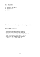
Item Checklist IDE Cable x 1, FDD Cable x 1 SATA 3Gb/s Cable x 1 I/O Shield * The items listed above are for reference only, and are subject to change without notice. Optional Accessories Š 2 Ports USB 2.0 Cable (Part Number: 12CR1-1UB030-51/R) Š 4 Ports USB 2.0 Cable (Part Number: 12CR1-1UB030-21 - Gigabyte GA-M61VME-S2 | Manual - Page 7
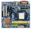
GA-M61VME-S2 (rev. 2.0) Motherboard Layout KB_MS ATX_12V Socket AM2 ATX COMA LPT VGA R_USB CPU_FAN USB LAN IT8716 AUDIO CI F_AUDIO HDA_SUR BIOS PCIE_1 Realtek 8201 CD_IN GA-M61VME-S2 PCIE_16 CLR_CMOS BATTERY PCI1 IDE DDRII_1 DDRII_2 SATAII 0 nVIDIA® GeForce 6100/ nForce 400 SATAII - Gigabyte GA-M61VME-S2 | Manual - Page 8
Block Diagram PCIe CLK (100 MHz) AMD Socket AM2 CPU CPU CLK+/-(200 MHz) DDRII 800/667/533/400 MHz DIMM Dual Channel Memory PCI Express x1 PCI Express x1 Bus x1 PCIe CLK (100 MHz) 1 PCI Express x1 LAN RJ45 PCI Bus Realtek 8201 Hyper Transport Bus VGA nVIDIA® GeForce 6100/ nForce 400 2 SATA - Gigabyte GA-M61VME-S2 | Manual - Page 9
instructions below: 1. Please turn off the computer and unplug its power cord. 2. When handling the motherboard , avoid touching any metal leads or connectors. 3. It is best to wear an electrostatic discharge (ESD) cuff when handling electronic components (CPU motherboard problem manual - Gigabyte GA-M61VME-S2 | Manual - Page 10
Š 1 front audio connector Š 1 CD In connector Š 1 S/PDIF In/Out connector Š 1 HDA_SUR connector Š 1 COMB connector Š 1 power LED connector Š 2 USB 2.0/1.1 connectors for additional 4 USB 2.0/1.1 ports by cables Š 1 Chassis Intrusion connector GA-M61VME-S2 (rev. 2.0) Motherboard - 10 - - Gigabyte GA-M61VME-S2 | Manual - Page 11
Note 3) The GA-M61VME-S2 supports up to PCI Express x1 mode. (please refer to the VGA cards support list on page 16~17) (Note 4) Whether the CPU Smart FAN Control function is supported will depend on the CPU you install. (Note 5) EasyTune functions may vary depending on different motherboards. - 11 - Gigabyte GA-M61VME-S2 | Manual - Page 12
the middle of the CPU and gently press the metal lever back into its original position. Please use extra care when installing the CPU. The CPU will not fit if positioned incorrectly. Rather than applying force, please change the positioning of the CPU. GA-M61VME-S2 (rev. 2.0) Motherboard - 12 - - Gigabyte GA-M61VME-S2 | Manual - Page 13
paste on the surface of the CPU. Install all the CPU cooler components (Please refer to the cooler manual for detailed installation instructions). Fig.2 Please connect the CPU cooler power connector to the CPU_FAN connector located on the motherboard so that the CPU cooler can properly function to - Gigabyte GA-M61VME-S2 | Manual - Page 14
are unable to insert the module, please switch the direction. The motherboard supports DDRII memory modules, whereby BIOS will automatically detect memory capacity and specifications. Memory modules are designed so when you wish to remove the DIMM module. GA-M61VME-S2 (rev. 2.0) Motherboard - 14 - - Gigabyte GA-M61VME-S2 | Manual - Page 15
GA-M61VME-S2 supports the Dual Channel Technology. After operating the Dual Channel Technology, the bandwidth of Memory Bus will double. Due to CPU 's instruction document firmly into expansion slot in motherboard. 4. Be sure the metal BIOS utility of expansion card from BIOS. 8. Install related driver - Gigabyte GA-M61VME-S2 | Manual - Page 16
-RX70128D GV-RX70P128D GV-RX80T256V GV-RX80L256V GV-RX80256D GV-RX55128D GV-RX85T256V-B GV-RC850T256D-B GV-RX13P256D-RH GV-RX16P256D-RH GV-RX18L256V-B GV-RX18T512V-B GA-M61VME-S2 (rev. 2.0) Motherboard - 16 - - Gigabyte GA-M61VME-S2 | Manual - Page 17
Gigabyte Gigabyte Gigabyte driver upgrade. For more information please contact your OS or device(s) vendors. LAN Port The provided Internet connection is Fast Ethernet, supporting use audio software to configure 2-/4-/6-/8-channel audio functioning. 2. To set up an 8 channel audio configuration, - Gigabyte GA-M61VME-S2 | Manual - Page 18
5) IDE 6) FDD 7) SATAII 0 / SATAII 1 8) PWR_LED 9) F_PANEL 10) F_AUDIO 11) CD_IN 12) SPDIF_IO 13) HDA_SUR 14) F_USB1 / F_USB2 15) COMB 16) CI 17) CLR_CMOS 18) BATTERY GA-M61VME-S2 (rev. 2.0) Motherboard - 18 - - Gigabyte GA-M61VME-S2 | Manual - Page 19
all components and devices are properly installed. Align the power connector with its proper location on the motherboard and connect tightly. The ATX_12V power connector mainly supplies power to the CPU. If the ATX_12V power connector is not connected, the system will not start. Caution! Please use - Gigabyte GA-M61VME-S2 | Manual - Page 20
to connect the CPU/system fan cable to the CPU_FAN/SYS_FAN connector to prevent CPU damage or system hanging instructions located on the IDE device). Before attaching the IDE cable, please take note of the foolproof groove in the IDE connector. 40 39 2 1 GA-M61VME-S2 (rev. 2.0) Motherboard - Gigabyte GA-M61VME-S2 | Manual - Page 21
the cable connects to the FDD drive. The types of FDD drives supported are: 360 KB, 720 KB, 1.2 MB, 1.44 MB and /s can provide up to 300 MB/s transfer rate. Please refer to the BIOS setting for the SATA 3Gb/s and install the proper driver in order to work properly. 7 1 SATAII 0 SATAII 1 1 7 - Gigabyte GA-M61VME-S2 | Manual - Page 22
NC HD (IDE Hard Disk Active LED) SPEAK (Speaker Connector) RES (Reset Switch) PW (Power Switch) MSG (Message LED/Power/Sleep LED) NC GA-M61VME-S2 (rev. 2.0) Motherboard Reset Switch IDE Hard Disk Active LED Pin 1: LED anode(+) Pin 2: LED cathode(-) Pin 1: Power Pin 2- Pin 3: NC Pin 4: Data(-) Open - Gigabyte GA-M61VME-S2 | Manual - Page 23
5 Line Out (R) 6 NC 7 NC 8 No Pin 9 Line Out (L) 10 NC By default, the audio driver is configured to support HD Audio. To connect an AC97 front panel audio module to this connector, please refer to the instructions on Page 73 about the software settings. - 23 - Hardware Installation - Gigabyte GA-M61VME-S2 | Manual - Page 24
-R 12) SPDIF_IO (S/PDIF In/Out Connector) The S/PDIF output is capable of providing digital audio to external speakers or compressed AC3 data to an external Dolby Digital Decoder. Use this feature 2 3 4 5 6 Definition Power No Pin SPDIF SPDIFI GND GND GA-M61VME-S2 (rev. 2.0) Motherboard - 24 - - Gigabyte GA-M61VME-S2 | Manual - Page 25
English 13) HDA_SUR (Surround Center Connector) Attach the connector of the 5.1/7.1 Surround Cable (optional) to this connector. Pin No. Definition 1 LEF_P 2 SURR_RR 3 CEN_P 2 14 4 SURR_LL 5 CEN_JD 1 13 6 SURR_JD 7 GND 8 -SUR_DET 9 GND 10 No Pin 11 GND 12 S_SURR_JD 13 - Gigabyte GA-M61VME-S2 | Manual - Page 26
Intrusion, Case Open) This 2-pin connector allows your system to detect if the chassis cover is removed. You can check the "Case Opened" status in BIOS Setup. Pin No. Definition 1 1 Signal 2 GND GA-M61VME-S2 (rev. 2.0) Motherboard - 26 - - Gigabyte GA-M61VME-S2 | Manual - Page 27
is incorrectly replaced. Replace only with the same or equivalent type recommended by the manufacturer. Dispose of used batteries according to the manufacturer's instructions. If you want to erase CMOS... 1. Turn off the computer and unplug the power cord. 2. Gently take out the battery and put it - Gigabyte GA-M61VME-S2 | Manual - Page 28
English GA-M61VME-S2 (rev. 2.0) Motherboard - 28 - - Gigabyte GA-M61VME-S2 | Manual - Page 29
BIOS, either Gigabyte's Q-Flash or @BIOS utility can be used. Q-Flash allows the user to quickly and easily update or backup BIOS without entering the operating system. @BIOS is a Windows-based utility that does not require users to boot to DOS before upgrading BIOS but directly download and update - Gigabyte GA-M61VME-S2 | Manual - Page 30
LAN KL:Move Enter :Accept ESC:Exit The Main Menu (For example: BIOS Ver. : F6a) Once you enter Award BIOS : Select Item F10: Save & Exit BIOS Setup menus described in this chapter are for reference only and may differ from the exact settings for your motherboard. GA-M61VME-S2 (rev. 2.0) Motherboard - Gigabyte GA-M61VME-S2 | Manual - Page 31
English „ Standard CMOS Features This setup page includes all the items in standard compatible BIOS. „ Advanced BIOS Features This setup page includes all the items of Award special enhanced features. „ Integrated Peripherals This setup page includes all onboard peripherals. „ Power Management - Gigabyte GA-M61VME-S2 | Manual - Page 32
Mode Support Halt On F10: Manual User can manually BIOS to automatically detect IDE/SATA devices during POST(default) • None Select this if no IDE/SATA devices are used and the system will skip the automatic detection step and allow for faster system start up. GA-M61VME-S2 (rev. 2.0) Motherboard - Gigabyte GA-M61VME-S2 | Manual - Page 33
3.5 inch double-sided drive; 2.88 M byte capacity. Floppy 3 Mode Support (for Japan Area) Disabled Normal Floppy Drive. (Default value) Drive A on the motherboard, or 640K for systems with 640 K or more memory installed on the motherboard. Extended Memory The BIOS determines how much - Gigabyte GA-M61VME-S2 | Manual - Page 34
BIOS Enter: Select F5: Previous Values +/-/PU/PD: Value F10: Save F6: Fail-Safe Defaults ESC: Exit F1: control Auto AMD Cool'n'Quiet driver manages clock and VID to -HDD. Legacy LAN Select your boot device priority by Legacy LAN. Disabled Disable GA-M61VME-S2 (rev. 2.0) Motherboard - 34 - - Gigabyte GA-M61VME-S2 | Manual - Page 35
function. (Default value) Enabled Enable Away Mode in Windows XP Media Center operating system. (Away Mode: Enables the when you install a PCI card and a PCI Express VGA card on the motherboard. PCI Slot Set Init display first to PCI. PEG Set Init display first Enable. - 35 - BIOS Setup - Gigabyte GA-M61VME-S2 | Manual - Page 36
x NV SATA 1 Primary RAID x NV SATA 1 Secondary RAID [Disabled] Enabled Enabled Item Help Menu Level` KLJI: Move Enter: Select F5: Previous Values +/-/PU/PD: Value F10: Save F6: Fail-Safe Defaults ESC: Exit F1: General Help F7: Optimized Defaults GA-M61VME-S2 (rev. 2.0) Motherboard - 36 - - Gigabyte GA-M61VME-S2 | Manual - Page 37
onboard audio function. (Default value) Disabled Disable this function. Onboard LAN Boot ROM This function decide whether to invoke the boot ROM of the onboard LAN chip. Enabled Enable this function. Disabled Disable this function. (Default value) Onboard Serial Port 1 Auto BIOS will - Gigabyte GA-M61VME-S2 | Manual - Page 38
Storage detect This option allows users to decide whether to detect USB storage devices, including USB flash drives and USB hard drives during POST. Enabled BIOS will scan all USB storage devices. (Default value) Disabled Disable this function. GA-M61VME-S2 (rev. 2.0) Motherboard - 38 - - Gigabyte GA-M61VME-S2 | Manual - Page 39
Enter [Soft-Off] Item Help Menu Level` KLJI: Move Enter: Select F5: Previous Values +/-/PU/PD: Value F10: Save F6: Fail-Safe Defaults ESC: Exit F1: General Help F7: Optimized Defaults ACPI Suspend Type S1(POS) , 1~31 Time (hh: mm: ss) Alarm : (0~23) : (0~59) : (0~59) - 39 - BIOS Setup - Gigabyte GA-M61VME-S2 | Manual - Page 40
system, the system will be in "Off" state. (Default value) Full-On When AC-power back to the system, the system always in "On" state. GA-M61VME-S2 (rev. 2.0) Motherboard - 40 - - Gigabyte GA-M61VME-S2 | Manual - Page 41
[Auto] [Auto] Item Help Menu Level` KLJI: Move Enter: Select F5: Previous Values +/-/PU/PD: Value F10: Save F6: Fail-Safe Defaults ESC: Exit F1: General Help F7: Optimized Defaults PCI 1 IRQ Assignment Auto (Default value) Set IRQ 3,4,5,7,9,10,11,12,14,15 to PCI 2. - 41 - BIOS Setup - Gigabyte GA-M61VME-S2 | Manual - Page 42
. Monitor system/CPU temperature at 90oC / 194oF. Disable this function. (Default value) CPU/SYSTEM FAN Fail Warning Disabled Disable the CPU/system fan fail warning function. (Default value) Enabled Enable the CPU/system fan fail warning function. GA-M61VME-S2 (rev. 2.0) Motherboard - 42 - - Gigabyte GA-M61VME-S2 | Manual - Page 43
speed with Easy Tune based on their requirements. (Default value) CPU Smart FAN Mode This option is available only when CPU Smart FAN Control is enabled. Auto BIOS autodetects the type of CPU fan you installed and sets the optimal CPU Smart FAN control mode for it. (Default value) Voltage Set - Gigabyte GA-M61VME-S2 | Manual - Page 44
(Y/NS)a?vNe & Exit Setup Exit Without Saving ESC: Quit F8: Q-Flash KLJI: Select Item F10: Save & Exit Setup Load Optimized Defaults Selecting this field loads the factory defaults for BIOS and Chipset Features which the system automatically detects. GA-M61VME-S2 (rev. 2.0) Motherboard - 44 - - Gigabyte GA-M61VME-S2 | Manual - Page 45
Setup Exit Without Saving ESC: Quit F8: Q-Flash KLJI: Select Item F10: Save & Exit Setup Change/Set/Disable Password When you select this only basic items. If you select "System" at "Password Check" in Advance BIOS Features Menu, you will be prompted for the password every time the system is - Gigabyte GA-M61VME-S2 | Manual - Page 46
Award Software ` Standard CMOS Features ` Advanced BIOS Features ` Integrated Peripherals ` Power Management Setup F10: Save & Exit Setup Abandon all Data Type "Y" will quit the Setup Utility without saving to RTC CMOS. Type "N" will return to Setup Utility. GA-M61VME-S2 (rev. 2.0) Motherboard - Gigabyte GA-M61VME-S2 | Manual - Page 47
will continue to install other drivers. System will reboot automatically after install the drivers, afterward you can install others application. For USB2.0 driver support under Windows XP operating system, please use Windows Service Pack. After install Windows Service Pack, it will show a question - Gigabyte GA-M61VME-S2 | Manual - Page 48
This page displays all the tools that Gigabyte developed and some free software, you can choose anyone you want and press "install" to install them. 3-3 Driver CD Information This page lists the contents of software and drivers in this CD-title. GA-M61VME-S2 (rev. 2.0) Motherboard - 48 - - Gigabyte GA-M61VME-S2 | Manual - Page 49
English 3-4 Hardware Information This page lists all device you have for this motherboard. 3-5 Contact Us Please see the last page for details. - 49 - Drivers Installation - Gigabyte GA-M61VME-S2 | Manual - Page 50
English GA-M61VME-S2 (rev. 2.0) Motherboard - 50 - - Gigabyte GA-M61VME-S2 | Manual - Page 51
yet easy to use tools such as 1) Overclocking for enhancing system performance, 2) C.I.A. and M.I.B. for special enhancement for CPU and Memory, 3) Smart-Fan control for managing fan speed control of both CPU cooling fan and North-Bridge Chipset cooling fan, 4) PC health for monitoring system - Gigabyte GA-M61VME-S2 | Manual - Page 52
of hard disk data. Supporting Microsoft operating systems including Windows XP/2000/NT/98/Me Modular BIOS v6.00PG, An Energy Star Ally Copyright (C) 1984-2006, Award Software, Inc. GA-M61VME-S2 F6a . . . . :BIOS Setup/Q- drivers as well as software. GA-M61VME-S2 (rev. 2.0) Motherboard - 52 - - Gigabyte GA-M61VME-S2 | Manual - Page 53
Windows 2000, be sure to execute the EnableBigLba.exe program from the driver CD before data backup. 2. It is normal that data backup takes longer time than data restoration. 3. Xpress Recovery2 is compliant with the GPL regulations. 4. On a few motherboards based on Nvidia chipsets, BIOS update - Gigabyte GA-M61VME-S2 | Manual - Page 54
v2.02 Flash Type/Size SST 25LF040A 512K Keep DMI Data Enable Update BIOS from Drive Sa0vefilBeI(Os)SfotounDdrive EnteFr l:oRppuyn A :Move ESC:Reset :Power Off HDD 0-0 Total size : 0 F5 : Refresh GA-M61VME-S2 (rev. 2.0) Motherboard Free size : 0 DEL : Delete - 54 - - Gigabyte GA-M61VME-S2 | Manual - Page 55
BIOS file matches your motherboard model. Step 2: The process of system reading the BIOS file from the floppy disk is displayed on the screen. When the message "Are you sure to update BIOS?" appears, press ENTER. The BIOS update F10: Save & Exit Setup Load Optimized Defaults Press Y to load BIOS - Gigabyte GA-M61VME-S2 | Manual - Page 56
Click "Update New BIOS" c. Please select "All Files" in dialog box while opening the old file. d. Please search for BIOS unzip file, downloading from internet or any other methods (such as: M61VMES2.F1). e. Complete update process following the instruction. GA-M61VME-S2 (rev. 2.0) Motherboard - 56 - Gigabyte GA-M61VME-S2 | Manual - Page 57
II, be sure that motherboard's model name in BIOS unzip file are the same as your motherboard's. Otherwise, your system won't boot. III. In method I, if the BIOS file you need cannot be found in @BIOSTM server, please go onto Gigabyte's web site for downloading and updating it according to method - Gigabyte GA-M61VME-S2 | Manual - Page 58
formatted floppy disk. (Note ) (c) Windows XP/2000 setup disk. (d) Driver CD for your motherboard. (Note ) (1) Installing SATA hard motherboard. Then connect the power connector from your power supply to the hard drive. (Note) Required for setting up RAID array. GA-M61VME-S2 (rev. 2.0) Motherboard - Gigabyte GA-M61VME-S2 | Manual - Page 59
: Select F5: Previous Values +/-/PU/PD: Value F10: Save F6: Fail-Safe Defaults ESC: Exit F1: General Help F7: Optimized Defaults Figure 2 The BIOS Setup menus described in this section may not show the exact settings for your motherboard. The actual BIOS Setup menu options you will see shall - Gigabyte GA-M61VME-S2 | Manual - Page 60
[PCI Slot] [64M] [Enable If No Ext PEG] Item Help Menu Level : Move Enter: Select F5: Previous Values +/-/PU/PD: Value F10: Save F6: Fail-Safe Defaults Figure 3 ESC: Exit F1: General Help F7: Optimized Defaults Step 3: Save and exit BIOS Setup. GA-M61VME-S2 (rev. 2.0) Motherboard - 60 - - Gigabyte GA-M61VME-S2 | Manual - Page 61
F10 to enter RAID setup utility" (Figure 4). Hit the F10 key to enter the RAID BIOS setup utility. MediaShield IDE ROM BIOS 6.87 Copyright (C) 2006 NVIDIA Corp. Detecting array ... Press F10 a RAID mode. The supported RAID modes include Mirroring selected, you can manually set the striping block - Gigabyte GA-M61VME-S2 | Manual - Page 62
]a11tNa..01O?..MM ST3120026AS ST3120026AS [Y] YES [N] NO [ ] Del Capacity 111.79GB 111.79GB [ESC] Quit [F6] Back [F7] Finish [TAB] Navigate [ ] Select [ENTER] Popup Figure 7 GA-M61VME-S2 (rev. 2.0) Motherboard - 62 - - Gigabyte GA-M61VME-S2 | Manual - Page 63
you created will appear (Figure 8). (Note: BBS stands for BIOS Boot Specification. This indicates that the boot device is defined in the BIOS.) Boot BBS MediaShield Utility Aug 21 2006 - Array List . Now, you can proceed to install the SATA controller driver and operating system. - 63 - Appendix - Gigabyte GA-M61VME-S2 | Manual - Page 64
disk: Use an alternative system and insert the GIGABYTE motherboard driver CD-ROM. From the CD-ROM drive folder, double click the MENU.exe file in the BootDrv folder (Figure 12). A command prompt window will open similar to that in Figure 11. GA-M61VME-S2 (rev. 2.0) Motherboard Figure 12 - 64 - - Gigabyte GA-M61VME-S2 | Manual - Page 65
you have prepared the SATA driver disk and configured BIOS settings, you are ready to install Windows 2000/XP onto your SATA hard drive with the SATA driver. The following is an example of Windows XP installation. Step 1: Restart your system to boot from the Windows 2000/XP Setup disk and press F6 - Gigabyte GA-M61VME-S2 | Manual - Page 66
use with Windows, press ENTER. S=Specify Additional Device Enter=Continue F3=Exit Figure 16 If a message appears saying one or some file(s) cannot be found, please check the floppy disk or copy the correct SATA driver again from the motherboard driver CD. GA-M61VME-S2 (rev. 2.0) Motherboard - 66 - Gigabyte GA-M61VME-S2 | Manual - Page 67
the next screen (Figure 17) appears, press ENTER to continue the SATA driver installation from the floppy disk. Windows Setup Setup will load support for the following mass storage device(s): NVIDIA RAID CLASS DRIVER (required) NVIDIA nForce Storage Controller (required) * To specify additional SCSI - Gigabyte GA-M61VME-S2 | Manual - Page 68
Out Rear Speaker Out Side Speaker Out Onboard Audio Audio Jacks on 5.1/7.1 Jacks Surround Cable For the microphone to work correctly, you MUST connect it to either the default Mic In jack or the Line In jack and configure it in the audio driver. GA-M61VME-S2 (rev. 2.0) Motherboard - 68 - - Gigabyte GA-M61VME-S2 | Manual - Page 69
procedure below uses Windows XP as the example operating system. ) Setting Up Stereo Speakers We recommend that you use the speaker with amplifier to acquire the best sound effect if the stereo output is applied. STEP 1 : After installation of the audio driver, you should find an Audio Manager icon - Gigabyte GA-M61VME-S2 | Manual - Page 70
pop up and ask you what type of equipment is connected. Choose a device depending on the type of speaker connected (4-channel audio consists of Front Speaker Out (Line Out) and Rear Speaker Out) and then click OK. The 4channel audio setup is completed. GA-M61VME-S2 (rev. 2.0) Motherboard - 70 - - Gigabyte GA-M61VME-S2 | Manual - Page 71
audio driver, you should find an Audio Manager icon in your system tray (you can also find the icon in Control Panel). Doubleclick the icon to open the Audio Control Panel. STEP 2: In the Audio Control Panel, click the Audio the audio jacks on the motherboard and the surround cable, a small window - Gigabyte GA-M61VME-S2 | Manual - Page 72
to the audio jacks on the motherboard and the surround cable, a small window will pop audio consists of Front Speaker Out (Line Out), Rear Speaker Out, Center/Subwoofer Speaker Out, and Side Speaker Out) then click OK. The 8-channel audio setup is completed. GA-M61VME-S2 (rev. 2.0) Motherboard - Gigabyte GA-M61VME-S2 | Manual - Page 73
Effect Configuration: At the Sound Effect menu, users can adjust sound option settings as desired. AC'97 Audio Configuration: To enable the front panel audio connector to support AC97 Audio mode, go to the Audio Control Panel and click the Audio I/O tab. In the ANALOG area, click the Tool icon and - Gigabyte GA-M61VME-S2 | Manual - Page 74
successfully 2 short: CMOS setting error 1 long 1 short: DRAM or M/B error 1 long 2 short: Monitor or display card error 1 long 3 short: Keyboard error 1 long 9 short: BIOS ROM error Continuous long beeps: DRAM error Continuous short beeps: Power error GA-M61VME-S2 (rev. 2.0) Motherboard - 74 - - Gigabyte GA-M61VME-S2 | Manual - Page 75
- 75 - Appendix English - Gigabyte GA-M61VME-S2 | Manual - Page 76
English GA-M61VME-S2 (rev. 2.0) Motherboard - 76 - - Gigabyte GA-M61VME-S2 | Manual - Page 77
- 77 - Appendix English - Gigabyte GA-M61VME-S2 | Manual - Page 78
: +86-29-85531943 FAX: +86-29-85539821 Shenyang TEL: +86-24-83992901 FAX: +86-24-83992909 y India GIGABYTE TECHNOLOGY (INDIA) LIMITED WEB address : http://www.gigabyte.in y Australia GIGABYTE TECHNOLOGY PTY. LTD. WEB address : http://www.gigabyte.com.au GA-M61VME-S2 (rev. 2.0) Motherboard - 78 - - Gigabyte GA-M61VME-S2 | Manual - Page 79
BYTE Technology Co., Ltd. in SERBIA & MONTENEGRO WEB address : http://www.gigabyte.co.yu y GIGABYTE Global Service System To submit a technical or non-technical (Sales/ Marketing) question, please link to : http://ggts.gigabyte.com.tw Then select your language to enter the system. - 79 - Appendix - Gigabyte GA-M61VME-S2 | Manual - Page 80
- 80 -
-
 1
1 -
 2
2 -
 3
3 -
 4
4 -
 5
5 -
 6
6 -
 7
7 -
8
-
9
-
10
-
11
-
12
-
13
-
14
-
15
-
16
-
17
-
18
-
19
-
20
-
21
-
22
-
23
-
24
-
25
-
26
-
27
-
28
-
29
-
30
-
31
-
32
-
33
-
34
-
35
-
36
-
37
-
38
-
39
-
40
-
41
-
42
-
43
-
44
-
45
-
46
-
47
-
48
-
49
-
50
-
51
-
52
-
53
-
54
-
55
-
56
-
57
-
58
-
59
-
60
-
61
-
62
-
63
-
64
-
65
-
66
-
67
-
68
-
69
-
70
-
71
-
72
-
73
-
74
-
75
-
76
-
77
-
78
-
79
-
80
 |
 |

GA-M61VME-S2
(rev. 2.0)
AMD Socket AM2 Processor Motherboard
User's Manual
Rev. 200
2
12ME-M61VMES2-200
2
R
*
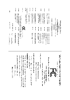
The WEEE marking on the product indicates this product must not be disposed of with user's other household waste
and must be handed over to a designated collection point for the recycling of waste electrical and electronic equipment!!
*
The WEEE marking applies only in European Union's member states.