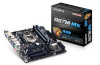
Gigabyte GA-Q87M-MK User Manual - Page 17
LPT Parallel Port Header, BAT Battery, DEBUG Debug Card Header, This header can connect a debug card.
 |
View all Gigabyte GA-Q87M-MK manuals
Add to My Manuals
Save this manual to your list of manuals |
Page 17 highlights
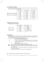
14) LPT (Parallel Port Header) The LPT header can provide one parallel port via an optional LPT port cable. For purchasing the optional LPT port cable, please contact the local dealer. Pin No. Definition Pin No. Definition Pin No. Definition 1 STB- 10 GND 19 ACK- 2 AFD- 11 PD4 20 GND 25 1 3 PD0 12 GND 21 BUSY 4 ERR- 13 PD5 22 GND 5 PD1 14 GND 23 PE 26 2 6 INIT- 15 PD6 24 No Pin 7 PD2 16 GND 25 SLCT 8 SLIN- 17 PD7 26 GND 9 PD3 18 GND 15) DEBUG (Debug Card Header) (Note) This header can connect a debug card. 11 1 12 2 Pin No. 1 2 3 4 5 6 Definition No Pin GND VCC3 LAD0 LAD1 LAD2 Pin No. 7 8 9 10 11 12 Definition LAD3 -LFRAME -PFMRST DB CLK DB_P_SENSOR NC 16) BAT (Battery) The battery provides power to keep the values (such as BIOS configurations, date, and time information) in the CMOS when the computer is turned off. Replace the battery when the battery voltage drops to a low level, or the CMOS vaYluoeusmmayayclenaortthbeeCaMccOuSravtaeluoersmbyaryembeovlionsgt.the battery: 1. Turn off your computer and unplug the power cord. 2. Gently remove the battery from the battery holder and wait for one minute. (Or use a metal object like a screwdriver to touch the positive and negative terminals of the battery holder, making them short for 5 seconds.) 3. Replace the battery. 4. Plug in the power cord and restart your computer. •• Always turn off your computer and unplug the power cord before replacing the battery. •• Replace the battery with an equivalent one. Danger of explosion if the battery is replaced with an incorrect model. •• Contact the place of purchase or local dealer if you are not able to replace the battery by yourself or uncertain about the battery model. •• When installing the battery, note the orientation of the positive side (+) and the negative side (-) of the battery (the positive side should face up). •• Used batteries must be handled in accordance with local environmental regulations. (Note) Whether this feature is supported depends on the product being received. - 17 -
-
 1
1 -
2
-
3
-
4
-
5
-
6
-
7
-
8
-
9
-
10
-
11
-
 12
12 -
 13
13 -
 14
14 -
 15
15 -
 16
16 -
 17
17 -
 18
18 -
 19
19 -
 20
20 -
 21
21 -
 22
22 -
23
-
24
-
25
-
26
-
27
-
28
-
29
-
30
-
31
-
32
-
33
-
34
-
35
-
36
 |
 |
